Audi Q7: Selector Mechanism, Checking
 WARNING
Risk of injury and accident by accidentally engaging a selector lever position with the engine running.
- Before working with the engine running, move the transmission into "P" and pull the parking brake button to activate the electro-mechanical parking brake.
- Pay attention to the safety precautions when driving. Refer to → Chapter "Safety Precautions when Working on Vehicle".
- All test points must be performed.
- When the specified values are not reached, check if the selector lever handle is installed correctly. Refer to → Chapter "Selector Lever Handle, Removing and Installing" and perform the "Guided Fault Finding" using the Vehicle Diagnostic Tester.
Overview:
- 1. Checking the gear locks/button functions.
- 2. Checking the selector mechanism functionality.
- 3. Checking the transmission range indicator.
- 4. Checking the display in the instrument cluster.
- 5. Checking the parking lock.
1. Checking the Gear Locks/Button Functions.
Test step 1.1
- Engine running, selector lever position "P" engaged, foot brake not pressed.
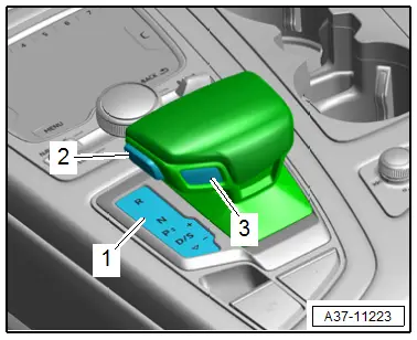
- Press the release button -2- and move the selector lever toward the rear.
The selector lever position "P" must remain selected.
Test step 1.2
- Engine running, selector lever position "P" engaged, release button -2- not pressed.
- Press the foot brake and move the selector lever toward the rear.
The selector lever position "P" must remain selected.
Test step 1.3
- Engine running, selector lever position "P" engaged, foot brake and release button -2- pressed.
- Engage the "D" position.
The selector lever position "D" must be displayed on the Selector Lever Transmission Range Display -Y5--1- and in the instrument cluster.
Test step 1.4
- Engine running, selector lever position "D" engaged, release button -2- not pressed.
- Push the selector lever forward in the direction "N":
The selector lever must be locked and the selector lever position "D" must remain selected.
Test step 1.5
- Engine running, selector lever position "D" engaged, release button -2- pressed.
- Engage the selector lever position "N".
The "N" position must be displayed on the Selector Lever Transmission Range Display -Y5--1- and in the instrument cluster.
Test step 1.6
- Engine running, selector lever position "D" engaged.
- Move the selector lever toward the rear.
The selector lever position "S" must be engaged, the display in the instrument cluster must switch from "D" to "S". By tipping the selector lever toward the rear again the selector lever position "D" must be engaged and displayed.
Test step 1.7
- Engine is running.
- Engage the selector lever position "P", "R", or "N".
- Move the selector lever into the tiptronic gate.
Shifting in the tiptronic gate is only possible from the "D" or "S" positions.
2. Function Test of the Selector Mechanism (Shiftlock)
Test step 2.1
- Engine running, selector lever position "D" engaged and vehicle speed greater than 3 km/h.
- Engage the "N" position. Then without pressing the release button -2- and brake, select the selector lever position "D".
It must be possible.
Test step 2.2
- Engine running, selector lever position "D" engaged and vehicle speed less than 3 km/h.
- Engage the selector lever position "N" for at least one second, do not press the foot brake and press the release button -2-.
Positions "R" and "D" must not be engaged.
Test step 2.3
- Engine running, selector lever position "N" engaged and vehicle speed less than 3 km/h.
- Press the foot brake and do not press the release button -2-.
Position "R" must not be engaged.
Position "D" must be able to be engaged.
Test step 2.4
- Engine running, selector lever position "M" engaged.
- Engage the selector lever position "P" to do so press the P button in the selector lever handle.
The selector lever position "P" must be engaged and displayed on the P button of the selector lever handle and in the instrument cluster. Additionally the P symbol between the positions "N" and "D/S" on the Selector Lever Transmission Range Display -Y5--1- must turn on.
The selector lever must move itself back into the automatic shift gate.
Test step 2.5
- Engine running, selector lever position "M" engaged.
- Move the selector lever to "+" and "-".
While driving the transmission range indicator in the instrument cluster must change each time a higher or lower gear is selected if the speed permits it.

3. Checking the Transmission Range Indicator
Test step 3.1
- Engine is running.
- Engage the positions "P", "R", "N", "D/S" and "+/-" one after the other.
The respective selector lever position must be significantly brighter than the other drive gear symbols.
Test step 3.2
- Engine is running.
- Engage the "P" position to do so press the button -3-.
The P symbol in the button in the selector lever handle must light up in white as a function lamp.
The P symbol in the Selector Lever Transmission Range Display -Y5--1- as a function lamp must be red.
In all other selector lever positions it must not be illuminated.

4. Checking the Display in the Instrument Cluster
Test step 4.1
- Engine running, selector lever position "P" engaged, foot brake not pressed.
- Press the release button -2- and move the selector lever in the direction of "D" or " R".
The following message must be displayed in the instrument cluster: "To select a position please press the foot brake and the locking button on the selector lever".
Test step 4.2
- Engine running, selector lever position "P" engaged, foot brake pressed.
- Do not press the release button -2- and move the selector lever in the direction of "D" or " R".
The following message must be displayed in the instrument cluster: "To select a position please press the foot brake and the locking button on the selector lever".
Test step 4.3
- Engine running, selector lever position "M" engaged.
- Press the button and at the same time the selector lever must be in "M" longer than 20 seconds (Not on tiptronic plus or tiptronic minus):
In the instrument cluster the following message must be displayed: "Bring the selector lever into the automatic position". Additional there is a warning tone.
5. Checking the Parking Lock.
Test step 5.1
- Engine is running, selector lever position "D", "S", "R", "M" engaged, vehicle is stationary.
- Turn off the engine.
The selector lever position "P" must automatically be engaged.
Test step 5.2
- Engine is running, selector lever position "N" engaged, vehicle is stationary.
- Turn off the engine and open the driver door.
The following message must be shown in the instrument cluster: "Before leaving engage P, otherwise the vehicle can roll". Additional there is a warning tone.

Emergency Release from P
 Note
Note
It is necessary to check the parking lock emergency release after performing any work on it or after removing and installing the transmission.
Releasing
 WARNING
The vehicle could start to roll and cause an accident.
Pull the parking brake button to activate the electro-mechanical parking brake.
- Remove the driver side floor mat.
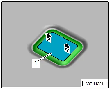
- Remove the cover -1- for the emergency release in direction of -arrows-.
- Remove the release tool -1- from the vehicle tool kit.
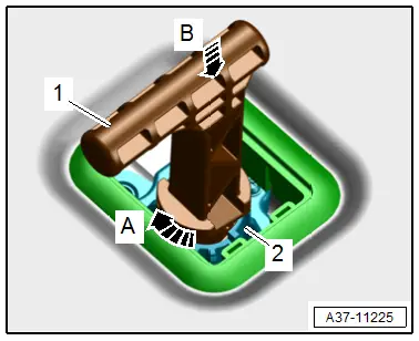
- Insert the release tool in the mount -2- for the emergency release as shown.
- The release tool is transverse to the direction of travel.
- Turn the release tool 90º -arrow A-, at the same time push downward in direction of -arrow B- until it engages.
- Release the parking lock.
 Note
Note
- When the parking lock is emergency released, the "N" mode is displayed in the instrument cluster.
- Additionally the following message is shown in the instrument cluster: "Danger of rolling away! P not possible. Set the parking brake".
Resetting the Release
- To lock the parking lock remove the release tool upward from the emergency release mount.
 Note
Note
When the parking lock is set "P" must be displayed in the instrument cluster and in the Selector Lever Transmission Range Display -Y5-.