Audi Q7: Solenoid Coupling, Removing and Installing
Special tools and workshop equipment required
- Clutch Module Puller -T40301-
- Clutch Module Centering Device -T40302-
- Test Adapter For Compressor Module -VAS6909A-
 Caution
This procedure contains mandatory replaceable parts. Refer to component overview prior to starting procedure.
Mandatory Replacement Parts
- O-ring - Solenoid coupling
Removing
- Supercharger secured to engine/transmission holder for repair work. Refer to → Chapter "Supercharger, Securing to Engine/Transmission Holder for Repair Work".
- Remove the coolant pipes from the supercharger. Refer to → Chapter "Supercharger Coolant Pipes, Removing and Installing".
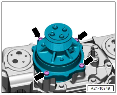
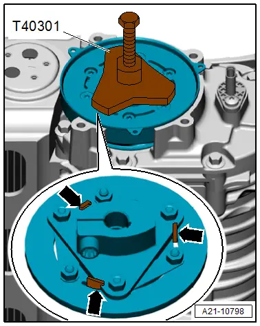
- Remove the bolts -arrows-.
- Slightly lift the solenoid coupling -1- and turn until one of the three trim bolts is accessible.
- Remove the first bolt -arrow-.
- Remove the remaining bolts, to do so turn the solenoid coupling respectively 1/3 turn further.
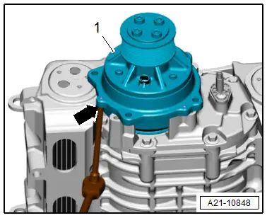
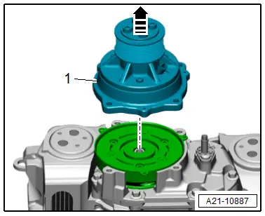
- Remove the solenoid coupling -1- in direction of -arrow-.
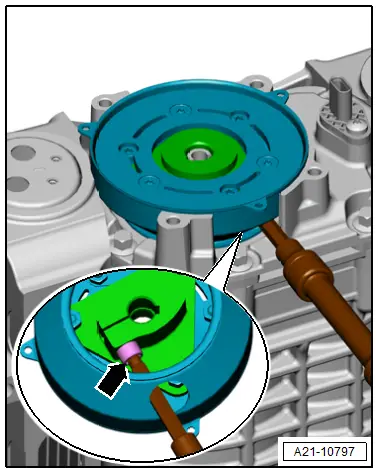
- Loosen the clamping screw -arrow- for the drive plate two turns by turning the drive plate in the respective position.
- Install the Clutch Module Puller -T40301- on the drive plate.
- The puller claws -arrows- must engage with the drive plate as shown.
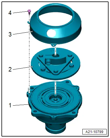
- Remove the drive plate -2-.
- Remove trim -1-.
- Remove the O-ring -arrow-.
Check the Sacrificial Liner and the Outer Friction Lining for Wear.
 Note
Note
Before reinstalling a used solenoid coupling the sacrificial liner and the outer friction lining must be checked for wear. If new solenoid coupling is installed this step does not apply.

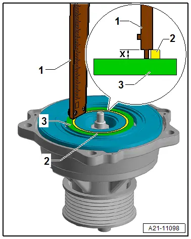
- Place the caliper -1- as shown on the highest point on the sacrificial liner -2- and measure the distance -X- to the friction lining -3-.
- Specified value -X-: minimum 0.2 mm.
- Perform the measurement all around on at least three locations.
- If specified value is not reached, replace the solenoid coupling.
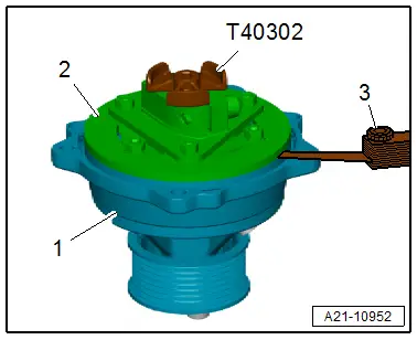
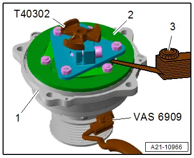
- Place the drive plate -2- on the solenoid coupling -1- and install the Clutch Module Centering Device -T40302- hand-tight.
- With the feeler gauge -3- check the distance of the outer friction lining to the outer friction surface.
- Specified value: minimum 0.2 mm.
- Perform the measurement all around on at least three locations.
- If specified value is not reached, replace the solenoid coupling.
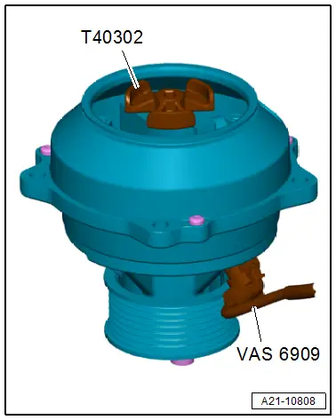
- The driver is still placed -2- on the solenoid coupling -1- and the Clutch Module Centering Device -T40302- is installed hand-tight.
- Connect the Test Adapter For Compressor Module -VAS6909- to a 12V battery or on the vehicle jump start terminal.
- Connect the Test Adapter for Compressor Module -VAS6909- connector with the solenoid coupling and switch on the power supply to the solenoid coupling.
 Caution
There is a risk of destroying the solenoid coupling.
- The solenoid coupling must not be connected longer than 15 minutes to the power supply.
- The current feed heats the solenoid coupling.
- With the feeler gauge -3- on the position shown in the illustration check the distance from the clamping hub -shown in blue- to the outer friction surface in the energized state.
- Perform this measurement on all three locations on the clamping hub.
- Specified value: maximum 1.3 mm
- If specified value is exceeded, replace the solenoid coupling.
- Switch off the Test Adapter For Compressor Module -VAS6909A-.
Installing
 Note
Note
Replace the O-ring after removing.
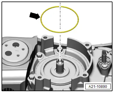
- Lay the O-ring -arrow- in the groove on the compressor housing.
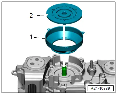
- Place the driver -2- on the solenoid coupling -1-.
- Place the trim -3- on the solenoid coupling and secure with three bolts -4-.
- Insert the Clutch Module Centering Device -T40302- in the drive plate and the solenoid coupling.
- The drive plate is centered to the solenoid coupling.
- Connect the Test Adapter For Compressor Module -VAS6909- to a 12V battery or on the vehicle jump start terminal.
- Connect the Test Adapter for Compressor Module -VAS6909- connector with the solenoid coupling and switch on the power supply to the solenoid coupling.
- With the power supply switched on the drive plate is secured on the solenoid coupling.
 Note
Note
- Pay attention during the assembly that the solenoid coupling current feed with the Test Adapter for Compressor Module -VAS6909- is not interrupted.
- Interrupting the solenoid coupling current feed with the Test Adapter for Compressor Module -VAS6909- may only take place when the clamping hub clamping screw is secured on the shaft.
 Caution
There is a risk of destroying the solenoid coupling.
- The solenoid coupling must not be connected longer than 15 minutes to the power supply.
- The current feed heats the solenoid coupling.
- Remove the Clutch Module Centering Device -T40302- with the power supply switched on.
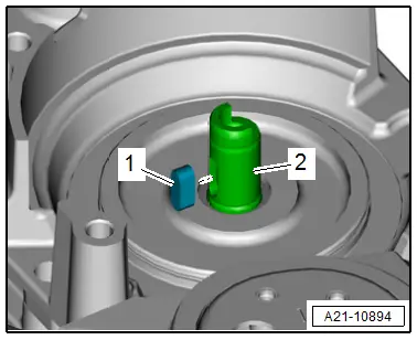
- Check that the coil spring -1- is seated correctly in the drive axle -2-.
- The drive axle must be free of oil and grease.
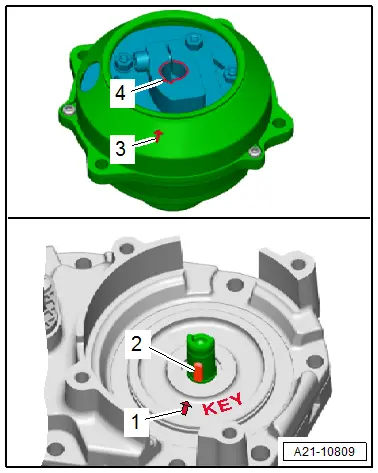
The following marks help with the allocation of the solenoid coupling driver to the supercharger shaft:
- Position the solenoid coupling drive plate so that the groove -4- for the coil spring alights with the arrow marking on the trim -3-.
- Position the supercharger so that the coil spring -2- points to the mark "KEY"-1-.
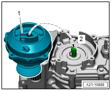
- Place the solenoid coupling drive plate -1- on the supercharger shaft -2--arrow-.
- With the power supply still switched on place the solenoid coupling on the supercharger and tighten the bolts -arrows-.
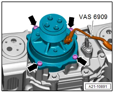
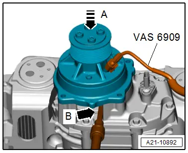
- With the power supply still switched on push the belt pulley by hand downward to the supercharger in direction of -arrow A- and at the same time tighten the clamping screw -arrow B-.
- Switch off the power supply, remove the Test Adapter for Compressor Module -VAS6909- from the solenoid coupling and from the power source.
- Install the coolant pipes to the supercharger. Refer to → Chapter "Supercharger Coolant Pipes, Removing and Installing".
Adapt the solenoid coupling after removing and installing or replacing:
- Connect the Vehicle Diagnostic Tester.
- Switch the ignition on.
- Select and start the Diagnostic operating mode.
- Select the Test plan tab.
- Select the button Individual tests and select the following tree structures one after the other:
- Drivetrain
- TFSI V6
- 01 - OBD-capable systems
- Simos Fuel Injection and Ignition
- Functions
- 01 - Supercharger clutch adaptation
Tightening Specifications
- Refer to → Chapter "Overview - Solenoid Coupling"

