Audi Q7: Spring, Removing and Installing
Spring, Removing and Installing, Coil Spring
Special tools and workshop equipment required
- Pneumatic/Hydraulic Foot Pump -VAS6179-
- Spring Tensioning System -VAS6274-
- 30 mm long centering spring -5- from the Spring Tensioning System - Audi Set -VAS6274/10-
- Supplement Set VAS6274/12 -VAS6274/12-, not shown
Removing
- Remove the shock absorber. Refer to → Chapter "Shock Absorber, Removing and Installing".
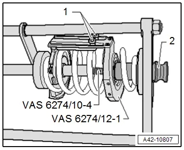
- Place the Supplement Set - Spreader Q7 -VAS6274/12-4- on the front transverse link, as shown.
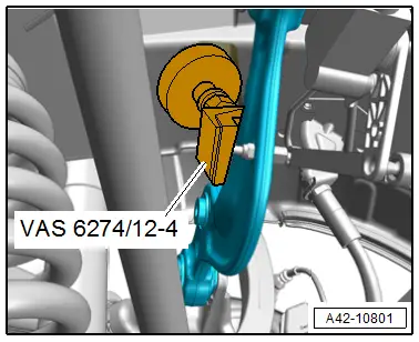
- Slide the securing lever back in the direction of -arrow- if necessary.
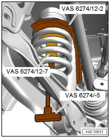
- Insert the Supplement Set - Thrust Plate With Securing Plate -VAS6274/12-2- from the supplement set from the outside, as shown.
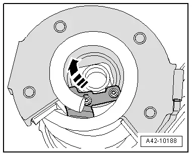
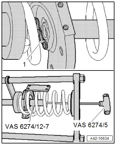
- Inset the Supplement Set - 89 mm Plunger -VAS6274/12-7- with the Spring Tensioning System - T-Bar -VAS6274/5- in the thrust plate. Slide the locking lever on the thrust plate back toward the outside (open).
- Press the locking lever in the direction of -arrow- to secure the piston.
- Turn the Supplement Set - Thrust Plate With Securing Plate -VAS6274/12-2- completely upward.

 Caution
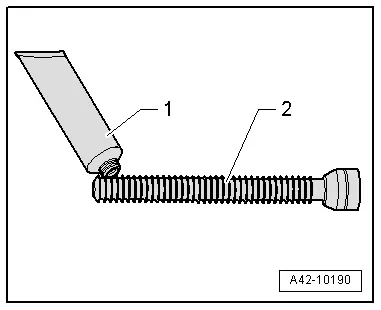
There is a risk of damaging the spindle due to missing or incorrect grease.
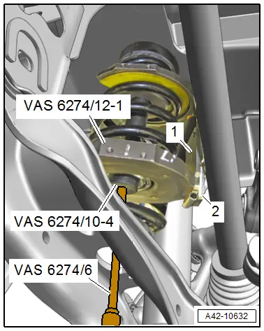
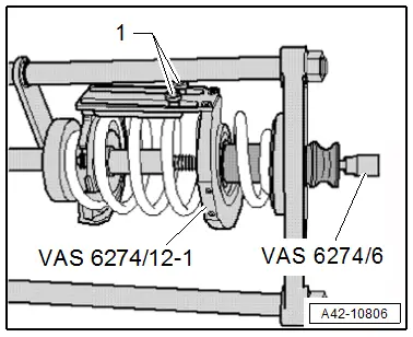
Coat the front area of the Spring Tensioning System - Audi Set - Spindle -VAS6274/10-4--Pos. 2- lightly with the accompanying grease -1- before removal and installation of each spring.
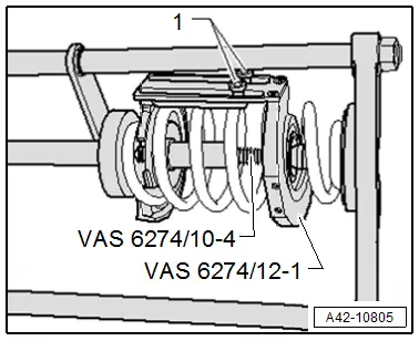
- Install the Supplement Set - Thrust Plate With Swivel Bearing - VAS6274/12-1- with the locking device brackets from the supplement set, as shown.
- The locking device brackets -1 and 2- from both thrust plates are parallel to each other.
- Thinly grease the Spring Tensioning System - Audi Set -VAS6274/10-4- in the front area and install hand tight with the Spring Tensioning System - Socket -VAS6274/6-.
 WARNING
Risk of accident!
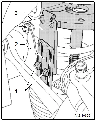
The coil spring may only be tensioned or released if both locking device brackets -2- and -3- are connected to each other using both bolts -1-.
- Install the bolts -1- for both the thrust plates locking device brackets -2 and 3- hand tight.
- Lightly tension the thrust plates using the Spring Tensioning System - Audi Set - Spindle -VAS6274/10-4-.
- Check if both coil springs are seated correctly in the pressure plates.
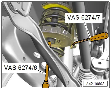
- Tension the coil spring with the Spring Tensioning System - Socket -VAS6274/6-, to do so counterhold with the Spring Tensioning System - Counterhold Tool -VAS6274/7-.
 WARNING
Risk of injury due to uneven tensioning of the coil springs.
- Do not use an impact wrench to tension the coil springs.
- Use a commercially available ratchet to tighten.
- Tension the coil spring until it can be removed.
 Caution
There is a risk of damaging the spring tensioning system when tensioning.
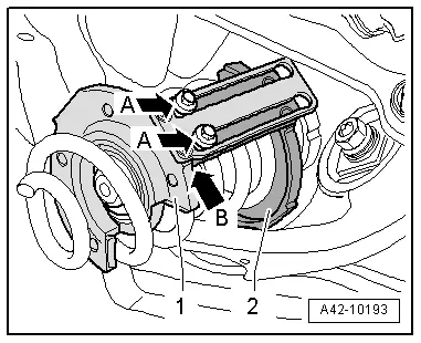
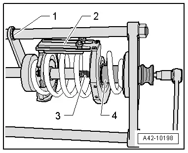
- The bolts -A arrows- must not contact the stop of the Supplement Set - Thrust Plate With Securing Plate -VAS6274/12-2--1-.
- The locking device brackets from the Supplement Set - Thrust Plate With Securing Plate -VAS6274/12-1--2- must not contact the stop -arrow B- of the thrust plate.
- Remove the coil spring forward and down.
Release the Tension of the Coil Spring in the Spring Tensioning System -VAS6274-.
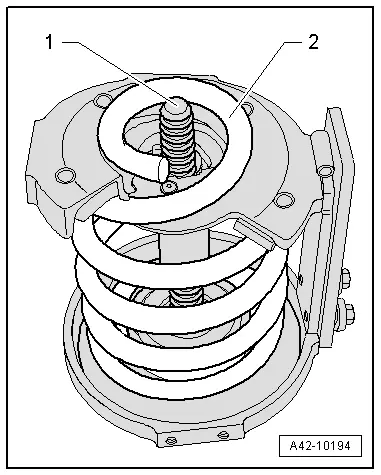
- Turn back the Spring Tensioning System - Audi Set - Spindle -VAS6274/10-4--1- slightly if necessary.
- The spindle must not project over the end of the coil spring -2-.

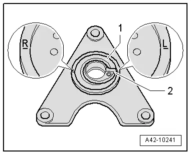
- Place the coil spring on the spring plate -1- so the stop -2- aligns with the corresponding mark.
 Note
Note
The opposite mark applies to the Audi Q7 coil springs.
R - Left Side of Vehicle
L - Right Side of Vehicle
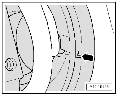
- Position the bottom of the coil spring in the Spring Tensioning System -VAS6274- at the -arrow- corresponding mark.
R - Left Side of Vehicle
L - Right Side of Vehicle
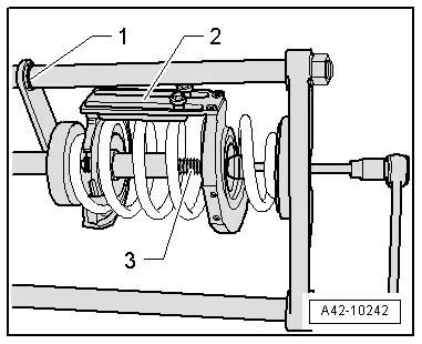
- Make a marking -1- with a waterproof felt-tip marker.
- The locking device -2- faces upward.
 Note
Note
- The mark is needed when tightening for installation.
- Ignore -3-.
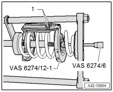
- Tighten the bolts -1- slightly by hand.
- Release the coil spring tension using the Spring Tensioning System - Socket -VAS6274/6-. Release the tension at the same time using the Spring Tensioning System -VAS6274- and the Pneumatic/Hydraulic Foot Pump -VAS6179-.
- After the tension on the coil spring is released, remove the Spring Tensioning System - Audi Set - Spindle -VAS6274/10-4-.
- Remove the locking device bolts -1- and the Supplement Set - Thrust Plate With Swivel Bearing -VAS6274/12-1-.
- Slide the locking lever -1- back.
- Remove the Supplement Set - 89 mm Plunger -VAS6274/12-7- with the Spring Tensioning System - T-Bar -VAS6274/5-.
- Release the coil spring completely.

Installing
Install in reverse order of removal and note the following:
- Insert the bottom of the coil spring in the Spring Tensioning System -VAS6274-. Refer to → Fig. "Coil spring and spring plate installation position" for the installation position.
- Position the coil spring in the Spring Tensioning System -VAS6274- at the -arrow- corresponding mark.
 Note
Note
The opposite mark applies to the Audi Q7 coil springs.
R - Left Side of Vehicle
L - Right Side of Vehicle

- Insert the Supplement Set - Thrust Plate With Securing Plate -VAS6274/12-2- and install the Supplement Set - 89 mm Plunger -VAS6274/12-7- with the Spring Tensioning System - T-Bar - VAS6274/5-.
- Secure the piston with the securing lever -1-.
- Insert the Supplement Set - Thrust Plate With Securing Plate -VAS6274/12-1-.
- Install the locking device bolts -1- loosely.
- Insert the Spring Tensioning System - Audi Set - Spindle -VAS6274/10-4-.
- Install the 130 mm long centering spring -2- until stop.
- Tighten the locking device bolts -1- lightly by hand. The locking device must face upward when tightening the coil spring.
- Tension the coil spring using the Spring Tensioning System - Socket -VAS6274/6-. At the same time tension using the Spring Tensioning System -VAS6274- and the Pneumatic/Hydraulic Foot Pump -VAS6179-.
 Caution
There is a risk of damaging the spring tensioning system when tensioning.
- The bolts from the locking device brackets must not contact the stop of the Supplement Set - Thrust Plate With Securing Plate -VAS6274/12-1-.
- The anti-twist mechanism bracket for the Supplement Set - Thrust Plate With Securing Plate -VAS6274/12-2- must also not lie on the stop for the Supplement Set - Thrust Plate With Securing Plate -VAS6274/12-1-.
- Only tighten the coil spring as far as the marking -1-. The locking device -2- must face up.
- When tensioning via the spindle -3-, make sure the centering sleeve -4- does not slip out of the Supplement Set - Thrust Plate With Securing Plate -VAS6274/12-1-.
- Release the Spring Tensioning System -VAS6274- and remove the coil spring with the tensioner.
- If necessary slightly re-tension the coil spring -2- via the Spring Tensioning System - Audi Set - Spindle -VAS6274/10-4--1-.
- The spindle must only project far enough over the coil spring that the upper spring plate can still rest completely on the coil spring.
- Bring the coil spring and the spring plate into the installation position. Refer to → Fig. "Coil spring and spring plate installation position".
- Install shock absorber. Refer to → Chapter "Shock Absorber, Removing and Installing".
- Tension the coil spring.
- Overview table for if an axle alignment is necessary. Refer to → Chapter "Need for Axle Alignment, Evaluating".
- Adjust the headlamps. Refer to → Electrical Equipment; Rep. Gr.94; Headlamps; Headlamp, Adjusting.
- Driver Assistance Systems Front Camera, Calibrating. Refer to → Chapter "Driver Assistance Systems Front Camera, Calibrating".
- Infrared System, Calibrating. Refer to → Chapter "Infrared System, Calibrating".
Spring, Removing and Installing, Air Spring
Special tools and workshop equipment required
- Torque Wrench 1331 5-50Nm -VAG1331-
- Torque Wrench 1332 40-200Nm -VAG1332-
Removing
 Note
Note
Follow the guidelines for clean working conditions. Refer to → Chapter "Guidelines for Clean Working Conditions".
- Remove the air suspension system. Refer to → Chapter "Air Suspension System, Filling and Bleeding".
- Remove the rear wheel. Refer to → Chapter "Wheels and Tires".
- Remove the drive axle. Refer to → Chapter "Drive Axle, Removing and Installing".
- Unclip the cap -2-.
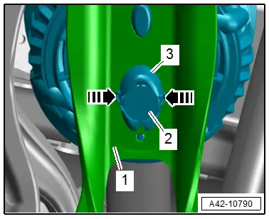
- Release the catches in direction of -arrows- and free up the air spring -3- on the lower transverse link -1-.
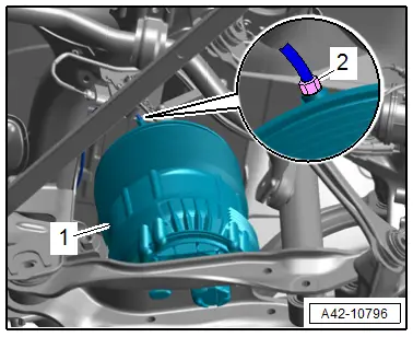
- Remove the connecting piece -2- from the rear air spring.
 Note
Note
If the connecting piece is removed separately (without the attached lines) check if the cutting ring has a loose components and is still in the threads and if necessary remove.
- Remove the air spring -1- downward.
Installing
Install in reverse order of removal and note the following:
- Air suspension system, filling. Refer to → Chapter "Air Suspension System, Filling and Bleeding".
 Note
Note
- The vehicle may be removed from the vehicle hoist only after the air springs have been filled again.
- Before filling the air spring, check the installation position. Refer to → Fig. "Air Spring Installed Position".
- Readapt the standard vehicle height. Refer to → Chapter "Standard Vehicle Height, Readapting".
Tightening Specifications
- Refer to → Chapter "Overview - Suspension Strut, Shock Absorber and Spring, Air Spring"
- Refer to → Chapter "Wheels and Tires"

