Audi Q7: Steering Gear, Removing and Installing
Special tools and workshop equipment required
- Torque Wrench 1331 5-50Nm -VAG1331-
- Torque Wrench 1332 40-200Nm -VAG1332-
- Engine and Gearbox Jack -VAS6931-
- Ball Joint Splitter -VAS251805-,
Removing
- Bring wheels in the straight position.
- Switch off the ignition.
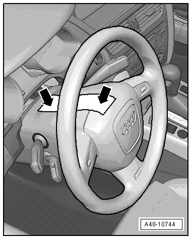
- Secure the steering wheel in the straight-ahead position using adhesive tape so that it does not turn -arrow-.
 Note
Note
- Use adhesive tape, which can be removed without leaving any adhesive residue.
- Be careful not to turn the steering wheel during the repair because the Airbag Spiral Spring/Return Spring with Slip Ring -F138- can become damaged.
- Remove the front wheels. Refer to → Chapter "Wheels and Tires".
- Remove the subframe crossbrace. Refer to → Chapter "Subframe Crossbrace, Removing and Installing".
 Caution
There is a risk of damaging the suspension components.
- If the subframe mount, the steering gear or the subframe crossbrace are not installed correctly, do not rest the vehicle on its wheels.
- The vehicle must not be supported on the subframe or the subframe crossbrace (for example using a floor jack).
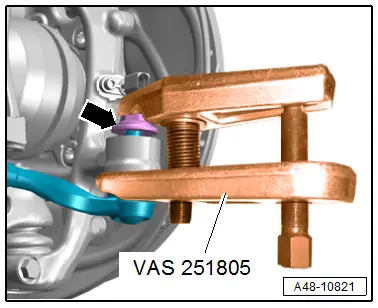
- To protect the threads remove the nut -arrow- on the joint pin tie rod head until it is flush with the threads of the joint pin.
 WARNING
Risk of injury from falling components!
When pressing off, the tie rod end loosens abruptly from the wheel bearing housing. Use, for example, the Engine and Gearbox Jack -VAS6931- to secure.
 Caution
There is a risk of damaging the ball joint puller.
Pay attention that both puller lever arms are parallel to each other when using greatest force.
- Remove the tie rod end with the Ball Joint Splitter -VAS251805- from the wheel bearing housing, not illustrated.
- Then remove the nut. To do so, counterhold at the joint pin using a 6 mm inner hex socket, if necessary.
- Repeat the procedure on the other side of the vehicle.
- Remove the nuts -arrows- and the stabilizer bar.
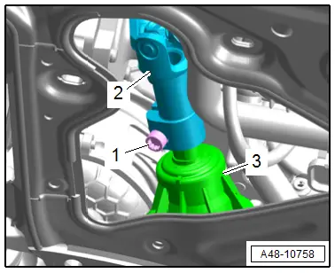
- Remove the bolt -1-.
- Remove the universal joint -2- of the steering intermediate shaft from the steering gear -3-.
- Release the safety catch, push the retainer down and disconnect the connectors -1 and 2- from the Power Steering Control Module -J500-.
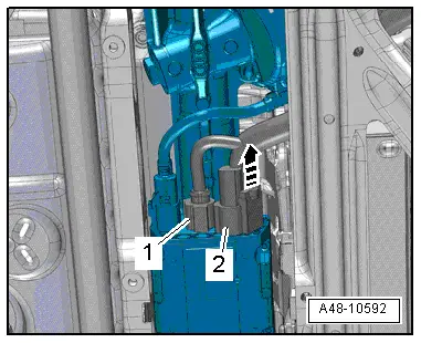
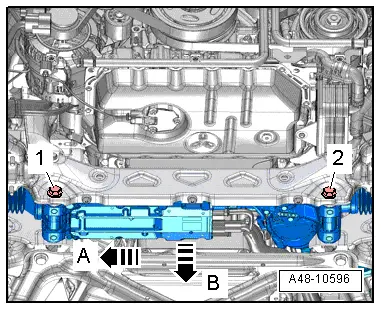
- Remove the bolts -1 and 2-.
 Caution
Risk of damaging the boot.
When removing the steering gear must not contact the boot.
- Push the steering gear slightly to the side in direction of -arrow A- and remove it downward in direction of -arrow B-.
Installing
Install in reverse order of removal and note the following:
- First install the bolts for the steering gear loosely then tighten.
- Install the steering intermediate shaft. Refer to → Chapter "Steering Intermediate Shaft, Removing and Installing".
After installing a new steering gear activate the steering gear with the Power Steering Control Module -J500-.
- Connect the Vehicle Diagnostic Tester.
- Switch the ignition on.
- Select and start the Diagnostic operating mode.
- Select the Test plan tab.
- Select the button Individual tests and select the following tree structures one after the other:
- Suspension
- Steering
- 01 - OBD-capable systems
- 44 - Power Steering Control Module J500
- 44 - Power Steering Control Module Functions
- 44 - Control Module, Replacing
- Start the selected program and follow the instructions in the display of the Vehicle Diagnostic Tester.
- Overview table for if an axle alignment is necessary. Refer to → Chapter "Need for Axle Alignment, Evaluating".
Tightening Specifications
- Refer to → Chapter "Overview - Steering Gear"
- Refer to → Chapter "Overview - Subframe"
Boot, Removing and Installing
Special tools and workshop equipment required
- Torque Wrench 1331 5-50Nm -VAG1331-
- Hose Clip Pliers -VAG1921-
Removing
 Caution
There is a risk of destroying the steering gear with a faulty boot by moisture and dirt entering.
- There must be visible grease film present on steering rack in area of splines. If the grease film is missing replace the steering gear.
- When cleaning the steering gear and surrounding components, dirt must not enter through the faulty boot or enter in the open steering gear, when removing the steering gear components and greasing the steering gear.
 Note
Note
Follow the guidelines for clean working conditions. Refer to → Chapter "Guidelines for Clean Working Conditions".
- Bring wheels in the straight position.
- Remove the front noise insulation. Refer to → Body Exterior; Rep. Gr.66; Noise Insulation; Noise Insulation, Removing and Installing.
- Remove the tie rod end. Refer to → Chapter "Tie Rod End, Removing and Installing".
- Clean the steering gear and the subframe in area of the boot.
- Remove the nut from the tie rod.
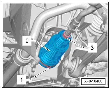
- Open the spring clamp -3- with the Hose Clip Pliers -VAG1921- and remove it.
- Remove the clamp -1- and remove the boot -2- outward from the steering gear.
Installing
Install in reverse order of removal and note the following:
 Note
Note
Replace the boot after removal.
 Caution
Risk of damaging the boot due to improper handling.
- Do not crumple the boot folds.
- Do not bring the boot into contact with hard or sharp objects.
- Check the seating of the boot on the steering gear for damage. Replace the steering gear if the seal seat is damaged.
- Coat the seating of the inner boot all around and evenly with Steering Gear Grease -G 052 168 A1-.
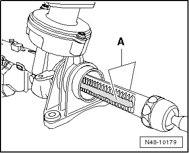
- Coat the steering rack on toothed side -A- and on the thrust piece side with Steering Gear Grease -G 052 168 A1- to do so turn the steering until stop.
- Bring wheels in the straight position.
- Slide the boot onto the steering gear housing with a new clamp.
- Make sure that the boot is seated correctly.
- The boot must fit in the groove and on the steering gear.
- Tension the inner clamp -1-. Refer to → Fig. "Tension the Inner Clamp Using the Clampling Pliers -VAG1682A-.".
- Secure the spring clip -3- on the boot -2- with the 9" Mobea Heater Hose Clamp Pliers -HCP10- at the same time pay attention to the installation position. Refer to → Fig. "Outer Boot Installation Position".
- Overview table for if an axle alignment is necessary. Refer to → Chapter "Need for Axle Alignment, Evaluating".

Tightening Specifications
- Refer to → Chapter "Overview - Steering Gear"
- Refer to → Chapter "Overview - Steering Gear, Tie Rods"
- Refer to → Chapter "Wheels and Tires"

