Audi Q7: Subframe, Servicing
Subframe Front Hydraulic Bonded Rubber Bushing, Replacing
 Note
Note
- If a bonded rubber bushing is faulty, then the bonded rubber bushing on the opposite side must also be replaced. Refer to the Parts Catalog for the allocation.
- Check the other bearing before switching out a defected bonded rubber bushing.
- If cracks, oil leaks or other damage is visible, this bonded rubber bushing must also be replaced.
Special tools and workshop equipment required
- Torque Wrench 1332 40-200Nm -VAG1332-
- Hydraulic Press -VAS6178-
- Pneumatic/Hydraulic Foot Pump -VAS 6179-
- Bearing Installer - Wheel Hub/Bearing Kit -T10205A-
- Bearing Installer - Wheel Hub/Bearing Kit - Spindle -T10205/8-1-
- Bearing Installer - Wheel Hub/Bearing Kit - Nuts -T10205/8-2-
- Assembly Tool -T40328-
- Assembly Tool - Pipe -T40328/1-
- Assembly Tool - Support Ring -T40328/3-
- Assembly Tool - Support Ring -T40328/7-
- Assembly Tool - Thrust Piece -T40328/10-
- Assembly Tool - Support -T40328/13-
Removing
- Remove the wheels. Refer to → Chapter "Wheels and Tires".
- Exhaust system without separating point: remove the muffler. Refer to → Rep. Gr.26; Exhaust Pipes/Mufflers; Muffler, Removing and Installing.
- Exhaust system with separating point: remove the exhaust pipe. Refer to → Rep. Gr.26; Exhaust Pipes/Mufflers; Overview - Muffler.
- Versions with air suspension: perform the system bleeding. Refer to → Chapter "Air Suspension System, Filling and Bleeding".
- Remove the left and right spring. Refer to → Chapter "Spring, Removing and Installing".
- Remove the diagonal braces. Refer to → Body Exterior; Rep. Gr.66; Underbody Trim Panel.
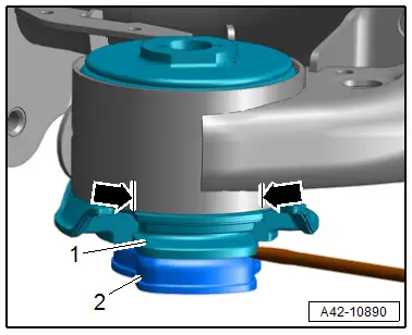
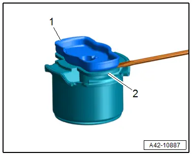
- Pry out the anti-twist mechanism -2- in the area of the retaining tabs with a screwdriver from the bonded rubber bushing alternating from side to side.
- Pry out the plastic insert -1- from the bonded rubber bushing.
- Mark the installation position of the hydraulic bonded rubber bushing on the subframe -arrows-, for example with a felt-tip marker.
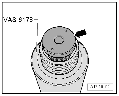
- If necessary, the support -arrow- with the small interior diameter must be removed from the Hydraulic Press -VAS6178- and the Assembly Tool - Support -T40328/13- for it must be installed.

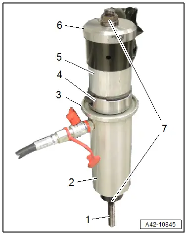
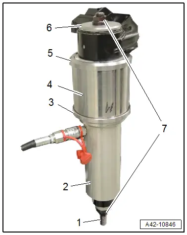
- Arrange the special tools as shown.
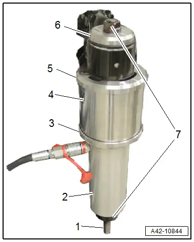
1 - Bearing Installer - Wheel Hub/Bearing Kit - Spindle -T10205/8-1-
2 - Hydraulic Press -VAS 6178-
3 - Assembly Tool - Support Ring -T40328/3-
4 - Assembly Tool - Pipe -T40328/1-
5 - Assembly Tool - Support Ring -T40328/7- The conical side must face upward and the ribs must fit into the openings in the rubber bonded bushing.
6 - Assembly Tool - Thrust Piece -T40328/10-. The opening faces the rubber bonded bushing.
7 - Bearing Installer - Wheel Hub/Bearing Kit - Nuts -T10205/8-2-
 WARNING
Risk of injury from falling components!
Hold the Hydraulic Press -VAS6178- firmly while pressing out.
Installing
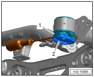
- Pry out the anti-twist mechanism -1- in the area of the retaining tabs -arrows- with a screwdriver from the bonded rubber bushing alternating from side to side.
- Pry out the plastic insert from the bonded rubber bushing.

- Arrange the special tools as shown.
1 - Bearing Installer - Wheel Hub/Bearing Kit - Spindle -T10205/8-1-
2 - Hydraulic Press -VAS 6178-
3 - Assembly Tool - Support Ring -T40328/3-
4 - Assembly Tool - Thrust Piece -T40328/8-. The ribs must engage in the bonded rubber bushing openings
5 - Bonded rubber bushing. Installation location. Refer to → Fig. "Subframe Hydraulic Front Bonded Rubber Bushing Installation Position".
6 - Assembly Tool - Thrust Piece -T40328/9-
7 - Bearing Installer - Wheel Hub/Bearing Kit - Nuts -T10205/8-2-
- Align the bonded rubber bushing with the markings made previously and push it in until the collar comes in contact with the bushing in the subframe without any gaps.
 Note
Note
- If necessary, tension and press over cylinder several times.
- To prevent damage to the outer race, while pushing in, pay attention that the bonded rubber bushing is not tilted.
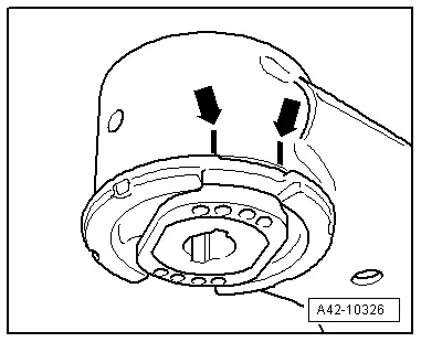
- The ends of the rubber bead on the bonded rubber bushing must align with the markings -arrows- on the subframe.
 Note
Note
Correct any paint damage on subframe with corrosion protection, primer and black top coat.
- Install the plastic insert and the anti-twist mechanism on the hydraulic bonded rubber bushing.
Further installation is the reverse order of removal.

Rear Bonded Rubber Bushing for Rear Final Drive, Removing and Installing
Special tools and workshop equipment required
- Torque Wrench 1332 40-200Nm -VAG1332-
- Hydraulic Press -VAS6178-
- Pneumatic/Hydraulic Foot Pump -VAS6179-
- Bearing Installer - Wheel Hub/Bearing Kit -T10205A-
- Assembly Tool -T40328-, not illustrated
Removing
- Remove the driveshaft from the rear final drive and tie it up. Refer to → Rear Final Drive; Rep. Gr.39; Driveshaft; Driveshaft, Removing and Installing.
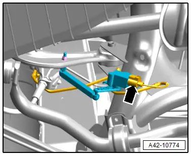
- Disconnect the left and right connector -arrow- from the rear vehicle level sensor and free up the wire.
Versions with Rear Axle Steering
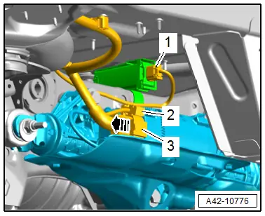
- Release the safety catch -arrow-, push the retainer down and disconnect the connector from -3- from the Rear Axle Steering Control Module -J1019-.
- Disconnect the connector -2- on the Rear Axle Steering Control Module -J1019-.
- Free up the wiring harness from the subframe.
Continuation for All Vehicles
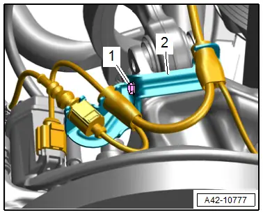
- Disconnect the connector -1- for the tire pressure monitoring antenna.
- Remove the left and right bolt -1- and free up the bracket -2- with the wires.
- Secure the subframe. Refer to → Chapter "Subframe, Securing".
- Lower the subframe a total of a maximum of 100 mm (3.93 in.).
- Pry out the anti-twist mechanism -2- in the area of the retaining tabs with a screwdriver from the bonded rubber bushing alternating from side to side.
- Pry out the plastic insert -1- from the bonded rubber bushing.
- Mark the installation position of the hydraulic bonded rubber bushing on the subframe -arrows-, for example with a felt-tip marker.

- If necessary, the support -arrow- with the small interior diameter must be removed from the Hydraulic Press -VAS6178- and the Assembly Tool - Support -T40328/13- for it must be installed.
- Arrange the special tools as shown.
1 - Bearing Installer - Wheel Hub/Bearing Kit - Spindle -T10205/8-1-
2 - Hydraulic Press -VAS6178-
3 - Assembly Tool - Support Ring -T40328/3-
4 - Assembly Tool - Pipe -T40328/1-
5 - Assembly Tool - Support Ring -T40328/2-. The conical side must face upward and the ribs must fit into the openings in the rubber bonded bushing
6 - Assembly Tool - Thrust Piece -T40328/4-
7 - Bearing Installer - Wheel Hub/Bearing Kit - Nuts -T10205/8-2-
 WARNING
Risk of injury from falling components!
- Hold the Hydraulic Press -VAS6178- firmly while pressing out.
- When pressing off, the bonded rubber bushing loosens abruptly from the subframe. Use, for example, the Engine and Gearbox Jack -VAS6931- to secure.
Installing
- Pry out the anti-twist mechanism -1- in the area of the retaining tabs -arrows- with a screwdriver from the bonded rubber bushing alternating from side to side.
- Pry out the plastic insert from the bonded rubber bushing.
- Arrange the special tools as shown.

1 - Bearing Installer - Wheel Hub/Bearing Kit - Spindle -T10205/8-1-
2 - Hydraulic Press -VAS 6178-
3 - Assembly Tool - Thrust Piece -T40328/8-. The ribs must engage in the bonded rubber bushing openings
4 - Bonded rubber bushing. Installation location. Refer to → Fig. "Subframe Hydraulic Front Bonded Rubber Bushing Installation Position".
5 - Assembly Tool - Thrust Piece -T40328/6-
6 - Bearing Installer - Wheel Hub/Bearing Kit - Nuts -T10205/8-2-
- Align the bonded rubber bushing with the markings made previously and push it in until the collar comes in contact with the bushing in the subframe without any gaps.
 Note
Note
- If necessary, tension and press over cylinder several times.
- To prevent damage to the outer race, while pushing in, pay attention that the bonded rubber bushing is not tilted.
- The ends of the rubber bead on the bonded rubber bushing must align with the markings -arrows- on the subframe.
 Note
Note
Correct any paint damage on subframe with corrosion protection, primer and black top coat.
- Install the plastic insert and the anti-twist mechanism on the hydraulic bonded rubber bushing.
Further installation is the reverse order of removal.