Audi Q7: Supercharger
Overview - Supercharger
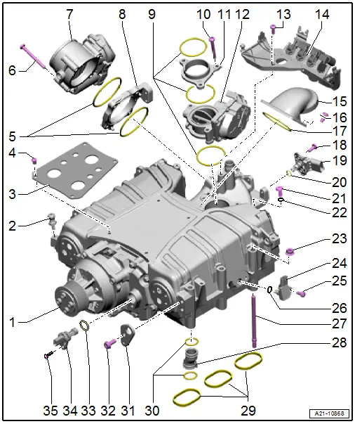
1 - Supercharger
- With charge air coolers
- Supercharger, Removing and installing. Refer to → Chapter "Supercharger, Removing and Installing".
- Overview - Charge Air Cooler. Refer to → Chapter "Overview - Charge Air System".
- Secured on the Engine and Gearbox Bracket -VAS6095A- for repair work. Refer to → Chapter "Supercharger, Securing to Engine/Transmission Holder for Repair Work".
- Secured on the Engine and Gearbox Bracket -VAS6095A- for leak test. Refer to → Chapter "Supercharger, Securing to Engine/Transmission Holder for Leak Test".
2 - Ball Pin
- 5 Nm
- For the engine cover
3 - Insulation Plate
4 - Bolt
- 5 Nm
5 - O-Rings
- Replace after removing
6 - Bolt
- Tightening specification. Refer to → Fig. " Throttle Valve Control Module -J338- - Tightening Specification".
7 - Throttle Valve Control Module -J338-
- Removing and installing. Refer to → Chapter "Throttle Valve Control Module -J338-, Removing and Installing".
8 - Intermediate Flange
9 - O-Rings
- Replace after removing
10 - Bolt
- Tightening specification and sequence. Refer to → Fig. " Regulating Flap Control Unit -J808- - Tightening Specification and Sequence".
11 - Intermediate Flange
12 - Regulating Flap Control Unit -J808-
- Removing and installing. Refer to → Chapter "Regulating Flap Control Unit -J808-, Removing and Installing".
13 - Bolt
- 9 Nm
14 - Bracket
- For change-over valves
15 - Connection
16 - Bolt
- Tightening specification and sequence. Refer to → Fig. " Regulating Flap Control Unit -J808- - Tightening Specification and Sequence".
17 - O-Ring
- Replace after removing
18 - Bolt
- 10 Nm
19 - Intake Air Temperature Sensor -G42-/ Manifold Absolute Pressure Sensor -G71-
- Removing and installing. Refer to → Chapter "Intake Air Temperature Sensor -G42-/Manifold Absolute Pressure Sensor -G71-, Removing and Installing".
20 - O-Ring
- Replace after removing
21 - Bleed Screw
- 1.5 to 3.0 Nm
- For the charge air cooler
22 - Gasket
- Replace after removing
23 - Nut
- 20 Nm
24 - Charge Air Pressure Sensor/Charge Air Pressure Sensor
- Cylinder bank 1 (right) Charge Air Pressure Sensor -G31-/Intake Manifold Temperature Sensor -G72-
- Cylinder bank 2 (left) Charge Air Pressure Sensor 2 -G447-/Intake Manifold Temperature Sensor 2 -G430-
- Removing and installing. Refer to → Chapter "Charge Air Pressure Sensor/Intake Manifold Temperature Sensor, Removing and Installing".
25 - Bolt
- 10 Nm
26 - O-Ring
- Replace after removing
27 - Stud Bolt
- 17 Nm
28 - Connection
- For the crankcase ventilation
- Installation position. Refer to → Fig. "Crankcase Ventilation Connection, Installing".
29 - Seals
- Replace after removing
30 - O-Rings
- Replace after removing
- Quantity 2 each
31 - Engine Lifting Eye
32 - Bolt
- 27 Nm
33 - O-Ring
- Replace after removing
34 - Turbocharger Speed Sensor 1 -G688-
- Removing and installing. Refer to → Chapter "Turbocharger Speed Sensor 1 -G688-, Removing and Installing".
- The opening cannot be used as an oil level display
35 - Bolt
- 10 Nm
Overview - Solenoid Coupling
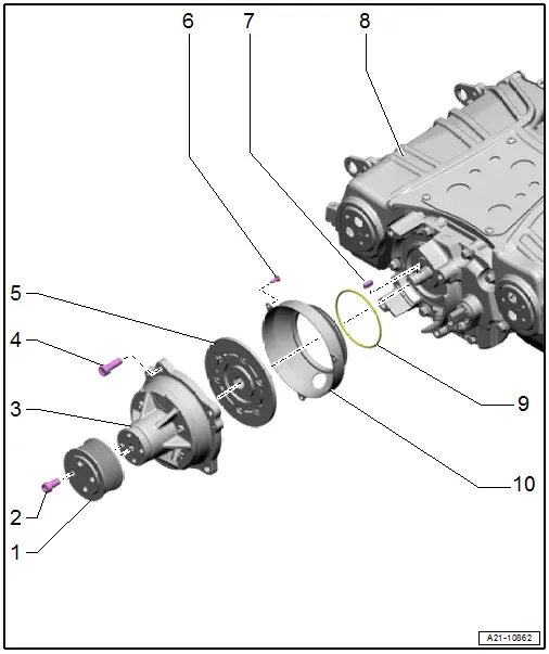
1 - Belt Pulley
- For the supercharger
- Removing and installing. Refer to → Chapter "Supercharger Belt Pulley, Removing and Installing".
2 - Bolt
- 20 Nm +90º
- Replace after removing
3 - Solenoid Coupling
- Removing and installing. Refer to → Chapter "Solenoid Coupling, Removing and Installing".
4 - Bolt
- 20 Nm
5 - Driver
- Tightening specification for the clamping screw. Refer to → Fig. "Tightening Specification for the Clamping Screw"
- Replace only together with -3-
- Do not loosen the threaded connections on the drive plate
- Replace the drive plate if the threaded connections are loosened
- Removing and installing. Refer to → Chapter "Solenoid Coupling, Removing and Installing".
- Clean the friction lining and friction surface before installing with brake cleaner
6 - Bolt
- 3.6 Nm
7 - Woodruff Key
8 - Supercharger
9 - O-Ring
- Replace after removing
10 - Trim
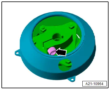
Tightening Specification for the Clamping Screw
- Tighten the clamping screw -arrow- to 20 Nm.
Overview - Rotor Unit
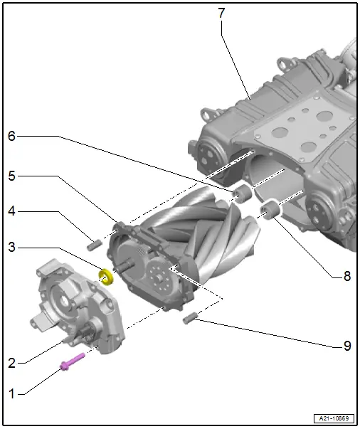
1 - Bolt
- 27 Nm
- Remove the old seal or locking fluid from the threads (for example with a thread tap)
- Before installing coat a few threads of the cleaned bolts with locking fluid. Refer to the Parts Catalog.
2 - Drive Head
- Replace the seal -3-, after every removal
- Removing and installing. Refer to → Chapter "Operating Head, Removing and Installing".
3 - Seal
- For the input shaft
- Replacing. Refer to → Chapter "Input Shaft Seal, Replacing".
4 - Alignment Sleeve
5 - Rotor Unit
- Removing and installing. Refer to → Chapter "Rotor Unit, Removing and Installing".
- After every removal and installation. Refer to → Chapter "Supercharger, Checking for Leaks".
- Remove the old seal or locking fluid from the threaded holes (for example with a thread tap)
6 - Needle Bearing
- For the rotor unit
- Replace together with the rotor unit. Refer to → Chapter "Rotor Unit, Removing and Installing".
7 - Supercharger Housing
8 - Needle Bearing
- For the rotor unit
- Replace together with the rotor unit. Refer to → Chapter "Rotor Unit, Removing and Installing".
9 - Alignment Sleeve

