Audi Q7: Supercharger, Removing and Installing
Special tools and workshop equipment required
- Hose Clamps - Up To 25 mm -3094-
- Engine Bung Set -VAS6122-
- Container of the Coolant Collection System -VAS5014- or the Shop Crane - Drip Tray -VAS6208-
- Hose Clip Pliers -VAS6362-
 Caution
This procedure contains mandatory replaceable parts. Refer to component overview prior to starting procedure.
Mandatory Replacement Parts
- O-rings - Intermediate Flange
Removing
 Note
Note
- Follow the guidelines for clean working conditions. Refer to → Chapter "Guidelines for Clean Working Conditions".
- Before testing or performing a repair, check all air duct pipes and hoses and vacuum lines for leaks and secure seating.
- Remove the supercharger ribbed belt. Refer to → Chapter "Ribbed Belt, Removing and Installing, Supercharger Ribbed Belt".
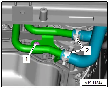
- Disconnect the coolant hoses -2- with Hose Clamps up to 25 mm Diameter -3094-.
- Remove the bolt -1-.
- Remove the reinforcement brace. Refer to → Body Exterior; Rep. Gr.50; Lock Carrier; Overview - Lock Carrier.
- Remove the engine cover. Refer to → Chapter "Engine Cover, Removing and Installing".
- Place the container of the Coolant Collection System -VAS5014- or the Shop Crane - Drip Tray -VAS6208- underneath.
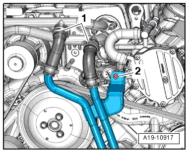
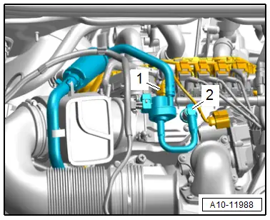
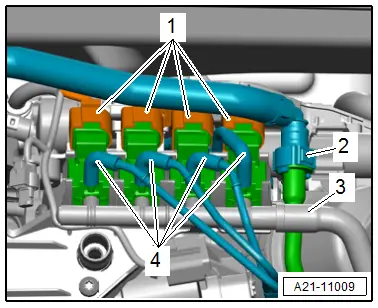
- Loosen the hose clamps -1- and remove the coolant hoses from the coolant pipes on the supercharger.
- Remove the bolt -2- and push the coolant pipe to the side.
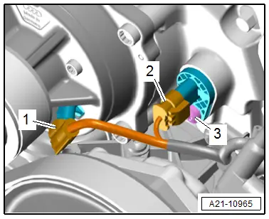
- Disconnect the connectors -1 and 2-.
 Note
Note
Ignore -3-.
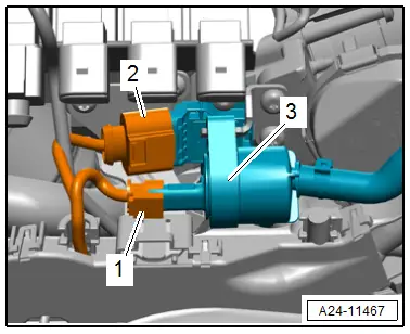
- Disconnect the connector -1- from the EVAP Canister Purge Regulator Valve 1 -N80-.
- Remove the vacuum hose -2- by pressing the release buttons on both sides.
- Disengage the EVAP Canister Purge Regulator Valve 1 -N80- from the bracket free it up and move to the side with the hoses connected.
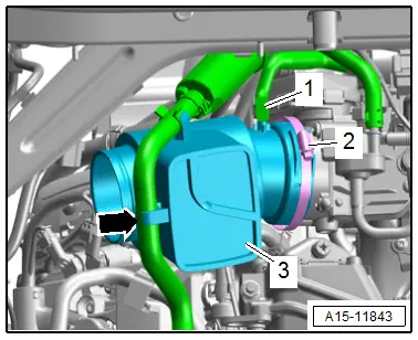
- Remove the vacuum hose -1- from the resonator -3-.
- Loosen the hose clamp -2- and remove the resonator.
 Note
Note
Ignore the -arrow-.
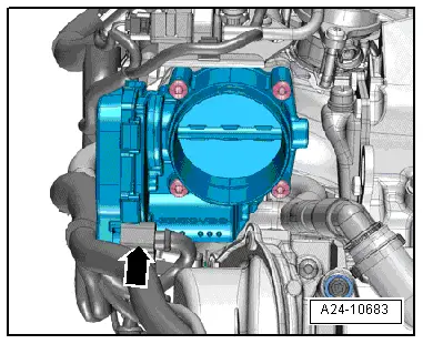
- Disconnect the connector -arrow- from the Throttle Valve Control Module -J338-.
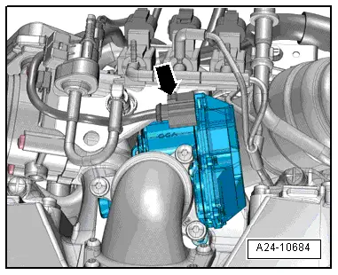
- Disconnect the connector -arrow- on the Regulating Flap Control Unit -J808-.
- Disconnect the connectors -1-.
 Note
Note
Mark the vacuum hoses for reinstallation.
- Disconnect the vacuum hoses -4- and the vacuum line -3-.
- Disconnect the vacuum hose -2- free up and move to the side.
- Release the catches in direction of -arrow- and push the wiring duct -1- to the rear.
- Disconnect the connector -1-.
- Remove the crankcase ventilation valve -3- from the bracket.
- Disconnect the connector -2- on the Intake Air Temperature Sensor -G42-/ Manifold Absolute Pressure Sensor -G71-.
- Disconnect the connectors -1 and 2- and free up the wire.
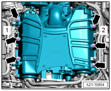
- Remove the nuts -arrows- and compressor with charge air cooler upward and at the same time pay attention to the clearance of the bypass valve.
- Seal off the opening on the supercharger and on the charge air circuit with plugs from the Engine Bung Set -VAS6122- or with clean cloths.
- Remove the noise insulation.
Installing
Install in reverse order of removal and note the following:
 Note
Note
- Replace the seals and O-ring after removal.
- Only remove the plugs or caps just before installing the respective lines.
- Secure all hose connections with hose clamps that match the ones used in series production. Refer to the Parts Catalog.
- Install the noise insulation.
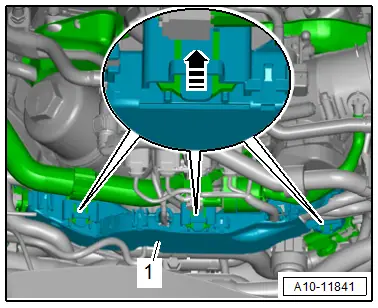
- Make sure the crankcase ventilation connection -1- is installed correctly when installing the supercharger. Refer to → Fig. "Crankcase Ventilation Connection, Installing".
- Install the left front coolant pipes. Refer to → Chapter "Front Left Coolant Pipes, Removing and Installing".
- Connections and wire routing. Refer to → Wiring diagrams, Troubleshooting & Component locations.
- Install the supercharger ribbed belt. Refer to → Chapter "Ribbed Belt, Removing and Installing, Supercharger Ribbed Belt".
 Note
Note
Used coolant cannot be used again.
- Fill with coolant.
Tightening Specifications
- Refer to → Chapter "Overview - Supercharger"
- Refer to → Chapter "Overview - Charge Air Hose Connections"
- Refer to → Body Exterior; Rep. Gr.50; Lock Carrier; Overview - Lock Carrier.
Supercharger, Checking for Leaks
Special tools and workshop equipment required
- Turbo System Tester Kit - VAG1687-Turbo System Tester Kit Adapter 4 - VAG1687/4-, Turbo System Tester Kit - Adapter 10 -VAG1687/10-, Turbo System Tester Kit - Adapter 13-1 -VAG1687/13-1- and Turbo System Tester Kit - Adapter 13-2 -VAG1687/13-2-
Procedure
- Supercharger secured on the Engine and Gearbox Bracket -VAS6095A- for the leak test. Refer to → Chapter "Supercharger, Securing to Engine/Transmission Holder for Repair Work".
- Regulating Flap Control Unit -J808- is installed. Refer to → Chapter "Regulating Flap Control Unit -J808-, Removing and Installing".
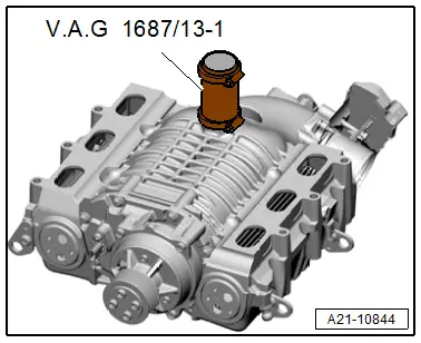
- Secure the Turbo System Tester Kit - Adapter 13-1 -VAG1687/13-1- on the bottom of the supercharger housing.
- Secure the hose connections with hose clamps.
 Note
Note
The supercharger is illustrated without the transmission holder.
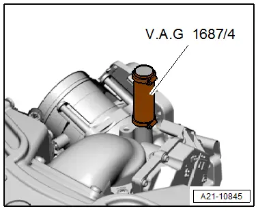
- Secure the Turbo System Tester Kit - Adapter 13-4 -VAG1687/13-4- on the top of the supercharger housing.
- Secure the hose connections with hose clamps.
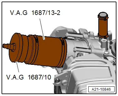
- Secure the Turbo System Tester Kit - Adapter 13-2 -VAG1687/13-2- with Turbo System Tester Kit - Adapter 10 -VAG1687/10- to the supercharger housing.
- Secure the hose connections with hose clamps.
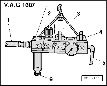
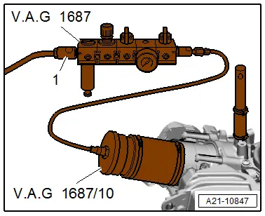
Prepare the Turbo System Tester Kit -VAG1687- as follows:
- Completely remove the pressure regulating valve -2- and close the valves -3- and -4-.
- Pull the knob in order to rotate the pressure regulating valve.

- Connect the Turbo System Tester Kit -VAG1687- as illustrated, to the compressed air using a commercially available intermediate piece -1-.
- If there is water in the viewing glass, open the water drain plug -6- and drain the water.
- Open the valve -3-.
 Caution
There is a risk of damage if the pressure is set too high.
The pressure must not exceed 0.5 bar (7.2 psi)!
- Set the pressure to 0.5 bar (7.2 psi) using the pressure regulating valve -2-.
- Open the valve -4- and wait until the test circuit is filled. Regulate the pressure to 0.5 bar (7.2 psi) again if required.
- Closes the valve -3-.
- The drop in pressure must not exceed 0.1 bar (1.45 psi) in 30 seconds.
- Inspect the charge air system for poorly sealed areas by listening, feeling, using commercially available leak detection spray or by using the Ultrasonic Tester -VAG1842S-.
 Note
Note
- Refer to the Owner's Manual for information on using the Ultrasonic Tester -VAG1842S-.
- Release the pressure in the test circuit by removing the hose coupling before removing the adapter.