Audi Q7: Camshaft Timing Chain, Removing and Installing
Removing
- The transmission is removed. Refer to → 8-Speed Automatic Transmission 0D5; Rep. Gr.37; Transmission, Removing and Installing; Transmission, Removing.
- Remove the lower timing chain cover. Refer to → Chapter "Lower Timing Chain Cover, Removing and Installing".
- Remove the camshaft timing chains from the camshafts. Refer to → Chapter "Camshaft Timing Chain, Removing from Camshafts".
 Caution
Risk of destroying the camshaft timing chain if the running direction is reversed on a used camshaft timing chain.
Use paint to mark arrows for the running direction of the left and right camshaft timing chains so they can be reinstalled. Do not mark the camshaft timing chain with a punch, notch or something similar.
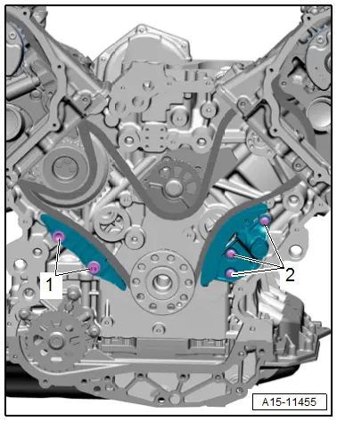
- Remove the Locking Pin -T40071- and the left camshaft timing chain.
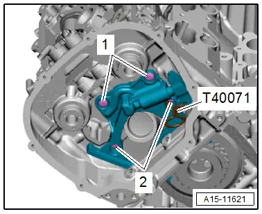
- Remove the bolts -1 and 2- and the right chain tensioner.

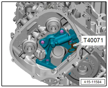
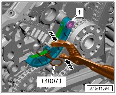
- Press the chain tensioner glide rail for the timing mechanism timing chain in the direction of -arrow- and secure the chain tensioner using a Locking Pin -T40071-.
- Remove the drive chain sprocket mounting pin bolt -1-.
- Remove the drive chain sprocket with the mounting pin and remove the right camshaft timing chain upward.

Installing
 Note
Note
- If the tensioner was removed from the chain tensioner, then note to the installation position: the hole in the bottom of the housing faces the chain tensioner and the piston faces the tensioning rail.
- Replace the bolts that were tightened with an additional turn after removing them.
 Caution
Risk of damaging valves and piston crowns.
If the camshafts are rotated, the crankshaft may not rest with any piston at "TDC".
- Install the left camshaft timing chain on the drive chain sprocket according to markings that were made during removal and guide it upward toward the cylinder head.
- Press the chain tensioner glide rail for the left camshaft timing downward and secure the chain tensioner using a Locking Pin -T40071-.

- Install the right camshaft timing chain on the drive chain sprocket according to markings that were made during removal and guide it upward toward the cylinder head.
- Install the drive chain sprocket. Refer to → Fig. "Mounting Pin for Right Camshaft Timing Chain Drive Chain Sprocket Installation Position".
- Tighten the drive chain sprocket mounting pin bolt -1-.
- Remove the Locking Pin -T40071-.
 Note
Note
Ignore the -arrow-.
- Install the chain tensioner on the right cylinder head.
- Tighten the bolts -1 and 2-.
Installation is performed in reverse order of removal, while noting the following:
- Position the camshaft timing chains on the camshafts.
- Install the lower timing chain cover. Refer to → Chapter "Lower Timing Chain Cover, Removing and Installing".
Tightening Specifications
- Refer to → Chapter "Overview - Camshaft Timing Chains"
Timing Mechanism Drive Chain, Removing and Installing
Special tools and workshop equipment required
- Locating Pins -T40116-
Removing
- The transmission is removed. Refer to → 8-Speed Automatic Transmission 0D5; Rep. Gr.37; Transmission, Removing and Installing; Transmission, Removing.
- Remove the lower timing chain cover. Refer to → Chapter "Lower Timing Chain Cover, Removing and Installing".
- Remove the camshaft timing chains. Refer to → Chapter "Camshaft Timing Chain, Removing and Installing".
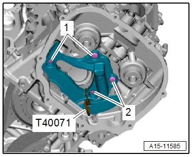
- Remove the bolts -1 and 2- and then remove the chain tensioner.
- Remove the power take-off drive chain. Refer to → Chapter "Oil Pump Drive Chain, Removing and Installing".
 Caution
Risk of destroying due to a reversed running direction on a used drive chain.
Use paint to mark the drive chain running direction with arrows for reinstallation.
- Remove the bolts -1- and the glide rail.
- Remove the bolts -2- and the chain tensioner.
- Remove the timing mechanism drive chain.
Installing
Install in reverse order of removal and note the following:
 Note
Note
Replace the bolts that were tightened with an additional turn after removing them.
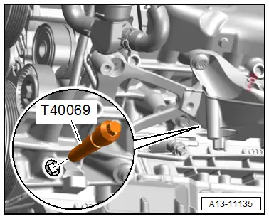
- Secure crankshaft in "TDC" position using Crankshaft Locking Pin -T40069-.
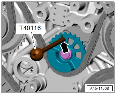
- Secure the balance shaft chain sprocket with the Locating Pins -T40116- in "TDC" point in the chain sprocket adjustment window -arrow-.
- Position the timing mechanism drive chain on the drive chain sprockets according to the markings made during removal.
- Install the glide rail and tighten the bolts -1-.
- Install the chain tensioner and tighten the bolts -2-.

- The Locating Pins -T40116- must be located approximately in the center of the adjustment window -arrow- in the balance shaft chain sprocket.
- The locating pin must never be to the left or the right. If necessary offset the chain by one tooth.
- Install the power take-off drive chain. Refer to → Chapter "Oil Pump Drive Chain, Removing and Installing".
- Install the camshaft timing chains. Refer to → Chapter "Camshaft Timing Chain, Removing and Installing".
- Install the lower timing chain cover. Refer to → Chapter "Lower Timing Chain Cover, Removing and Installing".

Tightening Specifications
- Refer to → Chapter "Overview - Timing Mechanism Drive Chain"
Oil Pump Drive Chain, Removing and Installing
Special tools and workshop equipment required
- Locking Pin -T40071-
 Caution
This procedure contains mandatory replaceable parts. Refer to component overview prior to starting procedure.
Mandatory Replacement Parts
- Bolt - Drive chain sprocket
Removing
- The transmission is removed. Refer to → 8-Speed Automatic Transmission 0D5; Rep. Gr.37; Transmission, Removing and Installing; Transmission, Removing.
- Remove the lower timing chain cover. Refer to → Chapter "Lower Timing Chain Cover, Removing and Installing".
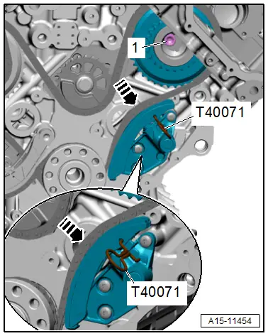
- Push down the chain tensioner spring with pliers in direction of -arrows- and lock with the Locking Pin -T40071-.
 Caution
Risk of destroying due to a reversed running direction on a used drive chain.
Use paint to mark the drive chain running direction with arrows for reinstallation. Do not mark the drive chain with a punch, notch or something similar.
- Remove the bolt -1- and the chain tensioner.
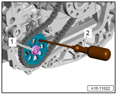
- Counterhold the chain sprocket with a screwdriver -2- and remove the bolt -1-.
- Remove the drive chain with the chain sprocket.
Installing
Install in reverse order of removal and note the following:
- Install the lower timing chain cover. Refer to → Chapter "Lower Timing Chain Cover, Removing and Installing".
Tightening Specifications
- Refer to → Chapter "Overview - Oil Pump Drive Chain"

