Audi Q7: Camshaft Timing Chain, Removing from Camshafts
Special tools and workshop equipment required
- Crankshaft Socket -T40058-
- Crankshaft Locking Pin -T40069-
- Locking Pin -T40071- (quantity: 2)
- Camshaft Clamp -T40133- (quantity: 2)
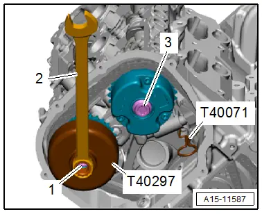
- Key -T40297-
 Caution
This procedure contains mandatory replaceable parts. Refer to component overview prior to starting procedure.
Mandatory Replacement Parts
- Bolts - Camshaft Adjuster
Removing
 Note
Note
- The camshaft timing chains stay on the engine in the following description.
- Even when only one cylinder head is worked on, the work procedure must nevertheless be performed on both cylinder banks.
- Remove the tower brace. Refer to → Suspension, Wheels, Steering; Rep. Gr.40; Suspension Strut and Upper Control Arm; Overview - Suspension Strut and Upper Control Arm.
- Remove the left and right timing chain covers. Refer to → Chapter "Left Timing Chain Cover, Removing and Installing".
- Remove the left and right cylinder head cover. Refer to → Chapter "Cylinder Head Cover, Removing and Installing".
- Remove the A/C compressor from the bracket and tie it up toward the front. Refer to → Heating, Ventilation and Air Conditioning; Rep. Gr.87; A/C Compressor; A/C Compressor, Removing and Installing at Bracket.
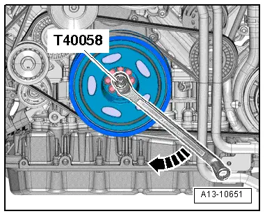
- Rotate the crankshaft in the direction of engine rotation in direction of -arrow- to "TDC" using the Crankshaft Socket -T40058- and an offset wrench.

 Note
Note
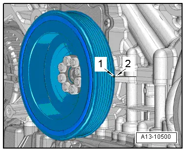
- Rotate the engine until the small notch -1- on the vibration damper aligns at the left of the housing separation point -2- between the cylinder block and the guide frame. This makes it easier to install the Crankshaft Locking Pin -T40069- later.
- The marking on the vibration damper is only there to help. The exact "TDC" location is only reached by installing the Crankshaft Locking Pin -T40069-.
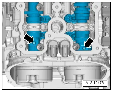
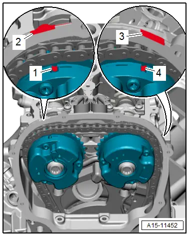
- The threaded holes -arrows- in all the camshafts must face upward.
 Note
Note
When the camshafts are not positioned as stated, turn the camshaft one turn farther and back to "TDC".
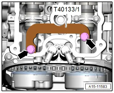
Cylinder Bank 1 (Right):
- Install the Camshaft Clamp -T40133- on cylinder head -arrows- and tighten to 25 Nm.
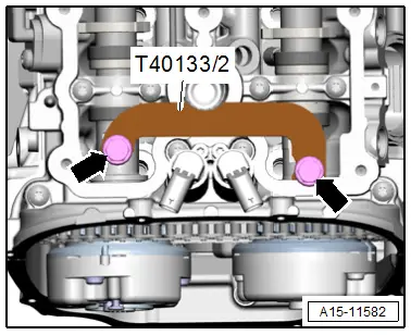
Cylinder Bank 2 (Left):
- Install the Camshaft Clamp 2 -T40133/2- on cylinder head -arrows- and tighten to 25 Nm.
Continuation for Both Cylinder Banks:
- Remove the plug -arrow- for the crankshaft "TDC" marking from the cylinder block.
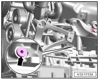
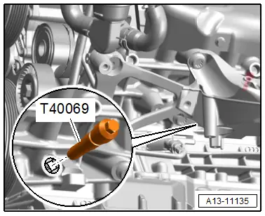
- Install the Crankshaft Locking Pin -T40069- in the hole and tighten to 20 Nm. Rotate the crankshaft back and forth slightly to center the pin completely, if necessary.

Cylinder Bank 1 (Right):
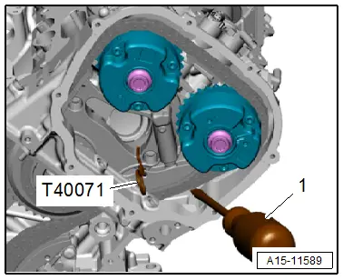
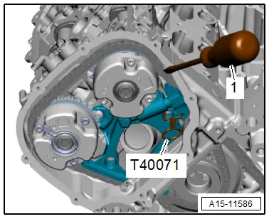
- Press the glide rail for the right camshaft timing chain tensioner all the way inward using a screwdriver -1- and secure the chain tensioner with a Locking Pin -T40071-.
 Note
Note
The toothed belt tensioner is lubricated with oil and should only be compressed slowly by applying constant pressure.
 Caution
Risk of damaging the camshafts.
Do not use the Camshaft Clamp -T40133- as a counterhold tool when loosening the bolt for the camshaft adjuster or the camshaft chain sprocket.
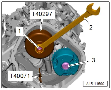
- To counterhold install the Timing Chain Tensioning Key -T40297- with a wrench -2- on the affected camshaft adjuster.
- Loosen the bolt -1- for the intake side camshaft adjuster.
- Counterhold with the Timing Chain Tensioning Key -T40297- to loosen the bolt -3- for the exhaust side camshaft adjuster.
 Caution
Risk of destroying the engine.
To prevent small parts from accidentally entering the engine through the opening in the timing chain compartment, cover the opening with a clean cloth.
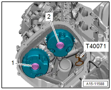
- Mark the installation position of the camshaft adjuster with paint for installation later.
- Remove the bolts -1 and 2- and remove both of the camshaft adjusters.
Cylinder Bank 2 (Left):
- Press the glide rail for the left camshaft timing chain tensioner all the way inward using a screwdriver -1- and secure the chain tensioner with a Locking Pin -T40071-.
 Note
Note
The toothed belt tensioner is lubricated with oil and should only be compressed slowly by applying constant pressure.
 Caution
Risk of damaging the camshafts.
Do not use the Camshaft Clamp -T40133- as a counterhold tool when loosening the bolt for the camshaft adjuster or the camshaft chain sprocket.
- To counterhold install the Timing Chain Tensioning Key -T40297- with a wrench -2- on the affected camshaft adjuster.
- Loosen the bolt -1- for the exhaust side camshaft adjuster.
- Counterhold with the Timing Chain Tensioning Key -T40297- to loosen the bolt -3- for the intake side camshaft adjuster.
 Caution
Risk of destroying the engine.
To prevent small parts from accidentally entering the engine through the opening in the timing chain compartment, cover the opening with a clean cloth.
- Mark the installation position of the camshaft adjuster with paint for installation later.
- Remove the bolts -1 and 2- and remove both of the camshaft adjusters.
Installing
 Note
Note
Replace the bolts that were tightened with an additional turn after removing them.
 Caution
Risk of damaging valves and piston crowns.
If the camshafts are rotated, the crankshaft may not rest with any piston at "TDC".
- Timing mechanism drive chain is installed. Refer to → Chapter "Timing Mechanism Drive Chain, Removing and Installing".
- Secure crankshaft in "TDC" position using Crankshaft Locking Pin -T40069-.

- Camshaft Clamp -T40133/1- tightened on cylinder bank 1 (right) to 25 Nm -arrows-.

- Camshaft Clamp -T40133/2- tightened on cylinder bank 2 (left) to 25 Nm -arrows-.

Cylinder Bank 1 (Right):
 Caution
The engine could be damaged.
The camshaft adjuster must only be installed according to the following work steps.
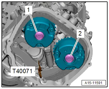
- Re-install the camshaft adjusters according to the marks applied during removal.
- The groove -1 and/or 4- in the camshaft adjuster must align with the adjustment window -2 and/or 3-.
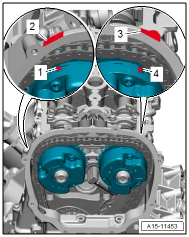
- Re-install the camshaft adjusters according to the marks applied during removal.
- Position the camshaft timing chain on the drive chain sprocket and the camshaft adjuster and loosely install the bolts -1 and 2-.
- Both camshaft adjusters must be able to still be rotated on camshaft and must not tip.
- Remove the Locking Pin -T40071-.

Cylinder Bank 2 (Left):
 Caution
The engine could be damaged.
The camshaft adjuster must only be installed according to the following work steps.
- Re-install the camshaft adjusters according to the marks applied during removal.
- the groove -1 and/or 4- in the camshaft adjuster must align with the adjustment window -2 and/or 3-.
- Re-install the camshaft adjusters according to the marks applied during removal.
- Position the camshaft timing chain on the drive chain sprocket and the camshaft adjuster and loosely install the bolts -1 and 2-.
- Both camshaft adjusters must be able to still be rotated on camshaft and must not tip.
- Remove the Locking Pin -T40071-.

Cylinder Bank 1 (Right):
- Position the Timing Chain Tensioning Key -T40297- on the camshaft adjuster of the exhaust camshaft.
- Position the Torque Wrench 1332 40-200Nm -VAG1332- with the Torque Wrench 1332 Insert - Open Ring Wrench - 24mm -VAG1332/9- on the Key Timing Chain Tensioning -T40297-.
- Have a second technician pre-tension the camshaft adjuster in the direction of -arrow- to 40 Nm.
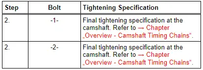
- Tighten the bolts as follows while the camshaft adjuster is still held under pretension.
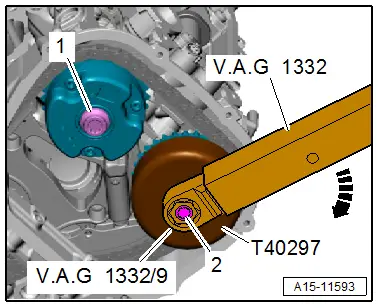

- Remove the Timing Chain Tensioning Key -T40297-.
- Remove the Camshaft Clamp -T40133/1--arrows-.

Cylinder Bank 2 (Left):
- Position the Timing Chain Tensioning Key -T40297- on the camshaft adjuster of the intake camshaft.
- Position the Torque Wrench 1332 40-200Nm -VAG1332- with the Torque Wrench 1332 Insert - Open Ring Wrench - 24mm -VAG1332/9- on the Key Timing Chain Tensioning -T40297-.
- Have a second technician pre-tension the camshaft adjuster in the direction of -arrow- to 40 Nm.
- Tighten the bolts as follows while the camshaft adjuster is still held under pretension.
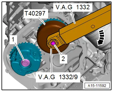

- Remove the Timing Chain Tensioning Key -T40297-.
- Remove the Camshaft Clamp -T40133/2--arrows-.

Cylinder Bank 1 (Right):
- Tighten the camshaft adjuster bolts on the right cylinder head as follows:

Cylinder Bank 2 (Left):
- Tighten the camshaft adjuster bolts on the left cylinder head as follows:

- Remove the Crankshaft Locking Pin -T40069-.

- Using the Crankshaft Socket -T40058- and an offset wrench, rotate the crankshaft two turns in the direction of engine rotation in direction of -arrow- until it is back at "TDC".
 Note
Note
If it is accidentally rotated beyond "TDC", rotate the crankshaft back approximately 30º and set it to "TDC" again.
Cylinder Bank 1 (Right):
- Install the Camshaft Clamp -T40133/1- on the cylinder head and tighten -arrows-.
- Tightening specification: 25 Nm.

Cylinder Bank 2 (Left):
- Install the Camshaft Clamp -T40133/2- on the cylinder head and tighten -arrows-.
- Tightening specification: 25 Nm.

Continuation for Both Cylinder Banks:
- Install the Crankshaft Locking Pin -T40069- directly in the hole.
- The Crankshaft Locking Pin -T40069- must engage in the securing hole on the crankshaft, otherwise repeat the adjustment.
- Remove the camshaft clamps from both cylinder heads.
- Remove the crankshaft locating pin.
Installation is performed in reverse order of removal, while noting the following:
- Install the cylinder head cover. Refer to → Chapter "Cylinder Head Cover, Removing and Installing".
- Install the left and right timing chain covers. Refer to → Chapter "Left Timing Chain Cover, Removing and Installing".
Tightening Specifications
- Refer to → Chapter "Overview - Camshaft Timing Chains"
- Refer to → Fig. " TDC Marking Plug - Tightening Specification"
- Refer to → Body Exterior; Rep. Gr.66; Noise Insulation; Overview - Noise Insulation.

