Audi Q7: Transmission Control
Component Location Overview - Transmission Control
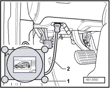
Data Link Connector
Component location: the data link connector for the Vehicle Diagnostic Tester is located in the footwell on the driver side.
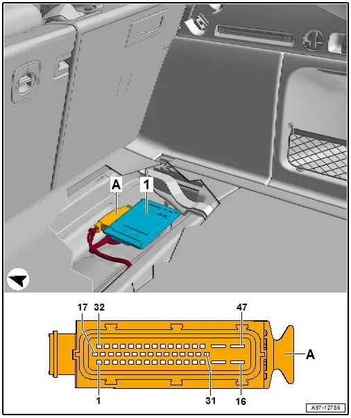
AWD Control Module -J492- in the A4
Component location: the AWD Control Module -J492--1- is in the luggage compartment in the center in front of the spare wheel well.
All Wheel Drive Control Module -J492-, Removing and Installing
- AWD Control Module -J492- component location. Refer to → Chapter "Component Location Overview - Transmission Control".
- Removing and installing is on the A4 Sedan.
- The ignition is off.
- Remove the luggage compartment floor covering.
- Remove the AWD Control Module -J492--1- from the bracket.
- Disconnect the connector -A- from the AWD Control Module -J492-.
- Install the AWD Control Module -J492- in reverse order of removal.
- If the AWD Control Module -J492- was replaced then additional work is necessary. Refer to → Chapter "AWD Control Module -J492-, Additional Work after Replacing".

AWD Control Module -J492-, Additional Work after Replacing
- Only perform the additional work only if the AWD Control Module -J492- was replaced.
- Connect the Vehicle Diagnostic Tester and turn on the ignition.
- Select the function 22 - AWD Electronics in the vehicle diagnostic tester under Guided Functions in the directory 22- Replacing Control Module.
- Follow all the instructions given by the Vehicle Diagnostic Tester exactly.
With the vehicle diagnostic tester the installed rear final drive is "adapted" on the AWD Control Module -J492-.
- A system check will take place when the 22 - Control Module, Replacing function is complete. If malfunctions appear, then use "Guided Fault Finding" to correct them.
