Audi Q7: Overview - Heater and A/C Unit
Overview - Front Heater and A/C Unit
 Note
Note
- Depending on vehicle equipment, there are different versions of the A/C system for the Audi Q7. Make sure to use the correct version and pay attention to the allocation of different components. Refer to → Chapter "A/C System Versions" and Parts Catalog.
- There are different versions of the front heater and A/C unit (for LHD and RHD vehicles, "Low", "Mid", "Mix" or "High" A/C systems etc.). Refer to the Parts Catalog.
 Caution
A/C system malfunctions in the case of interchanged control motors and/or connectors. Refer to → Chapter "Main Wiring Diagram for A/C System Actuators".
- The adjustment motors and connectors are identical. If they are installed or connected incorrectly, the corresponding doors cannot be properly adapted and/or activated.
- Clearly label the actuators and connectors prior to removal to prevent incorrect installation.
 Caution
There will be a problem when installing the wiring harness or when operating the vehicle with an incorrectly installed wiring harness.
- Document the routing of the wiring harness before removing for example by taking pictures.
- Install the wiring harness according to the prepared pictures and secure in the corresponding brackets.
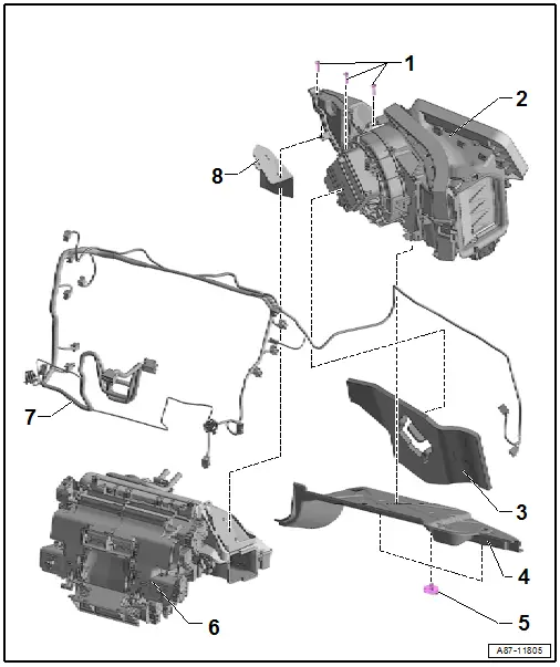
1 - Bolt
- 1 Nm
2 - Air Intake Housing
- Removing and installing the air intake housing from the heater and A/C unit. Refer to → Chapter "Air Intake Housing from Heater and A/C Unit, Removing and Installing".
To remove from the air distribution box
- Remove the wiring harness from both adjustment motors on the air intake housings (mark the routing beforehand).
- Remove the bolts -item 1-.
Before assembling
- Check the insulation -item 8- for damage and the correct installation
- Check the groove / spring connection on the air intake housing and on the air distribution box for damage.
 Note
Note
- Damaged or improperly joined connections can result in noises during operation.
- Fill (seal) small damages on the groove / spring connections carefully for example with a Silicone Adhesive -D 176 001 A3-. Refer to the Parts Catalog.
- The smallest leak on the groove / spring connection may cause whistling noise due to escaping air. Coat the connecting surfaces lightly with silicone grease (part number G 000 405 A2). Refer to the Parts Catalog.
3 - Insulation
- Removing and installing. Refer to → Chapter "Fresh Air Blower -V2- with Fresh Air Blower Control Module -J126-, Removing and Installing".
4 - Acoustic Cover
- Removing and installing. Refer to → Chapter "Dust and Pollen Filter, Removing and Installing".
5 - Screw Clips
- Removing and installing. Refer to → Chapter "Dust and Pollen Filter, Removing and Installing".
6 - Heater and A/C Unit Air Distribution Box with Evaporator
- There are different versions. Refer to the Parts Catalog.
This illustration shows the version:
- For LHD vehicles
- For vehicles with a "Mix" or "High" A/C system
- with installed adjustment motors and corresponding brackets
- with Auxiliary Heater Control Module -J604- ) with Auxiliary Heater Heating Element -Z35-)
- Removing and installing the evaporator housing from the air distribution box. Refer to → Chapter "Evaporator, Removing and Installing".
- Refer to → Chapter "Overview - Front Actuators"
7 - Wiring Harness, Heater and A/C Unit
- Different versions (for example for vehicles with a "Low" or "Mid" or a "Mix" or "High" A/C system, with and without a Auxiliary Heater Control Module -J604-. Refer to the Parts Catalog.
 Caution
Interchange of the wire connections to the temperature sensors or the connectors at the adjustment motors results in problems regarding the regulation of the A/C system.
- Interchanged connectors at the adjustment motors or the temperature sensors are not identified as malfunctions by the Front A/C Display Control Head -E87-.
- Prior to disconnecting connectors or removing electrical components, clearly label them in order to rule out confusion.
- Before removing the connector or removing the wiring harness, document the routing for example by taking pictures.
- Mark the allocation before disconnecting the connectors (danger of interchange, connectors of same shape for different motors and temperature sensor).
- Secure the wiring harness at the mounting points on the housing. With cable ties or at the mounts so that it cannot come into contact with any moving parts.
- With connection to the Front A/C Display Control Head -E87-. Refer to → Wiring diagrams, Troubleshooting & Component locations.
This illustration shows the version:
- For LHD vehicles
- For vehicles with a "Mix" or "High" A/C system
- For vehicles with Auxiliary Heater Control Module -J604- (with Auxiliary Heater Heating Element -Z35-)
- Removing and installing the air intake housing from the air distribution box. Refer to → Chapter "Air Intake Housing from Heater and A/C Unit, Removing and Installing".
8 - Insulation
- Installed between the air duct in the air distribution box and in the resonator chamber present in the air distribution box.
Overview - Front Heater and A/C Unit Attachments, Air Distribution Box, Heat Exchanger etc.
 Note
Note
- Depending on vehicle equipment, there are different versions of the A/C system for the Audi Q7. Make sure to use the correct version and pay attention to the allocation of different components. Refer to → Chapter "A/C System Versions" and Parts Catalog.
- There are different versions of the front heater and A/C unit (for LHD and RHD vehicles, "Low", "Mid", "Mix" or "High" A/C systems etc.). Refer to the Parts Catalog.
- The following illustration shows the air distribution box from the heater and A/C unit with the evaporator without the different adjustment motors, bracket and lever. Overview of the adjustment motors for the different versions of the front heater and A/C unit. Refer to → Chapter "Overview - Front Actuators".
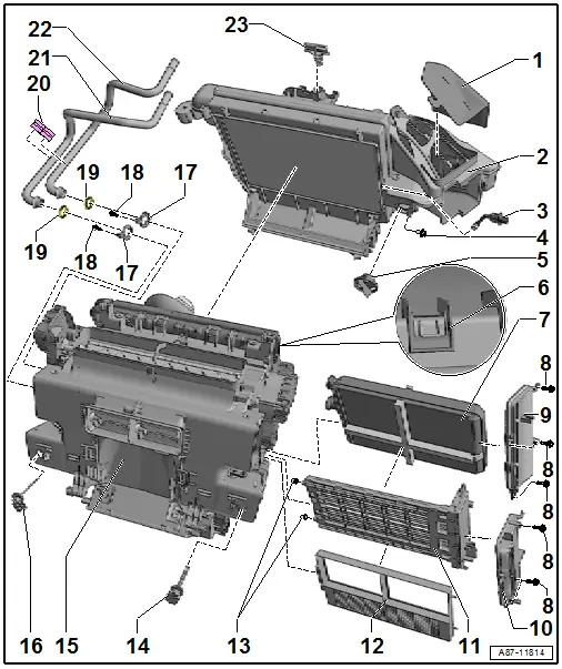
1 - Insulation
- Between the air duct in the air distribution box and in the resonator chamber present in the air distribution box.
2 - Evaporator Housing
- With the evaporator installed by the manufacturer
 Note
Note
There are different versions of the evaporator from the manufacturer and the replacement evaporator. Refer to → Chapter "Evaporator in Front Heater and A/C Unit, Removing and Installing".
- Depending on the version disassembling further may not be required. Refer to → Chapter "Overview - Evaporator Housing".
- Removing and installing the evaporator. Refer to → Chapter "Evaporator in Front Heater and A/C Unit, Removing and Installing".
- Refer to → Chapter "Heater and A/C Unit, Removing and Installing"
3 - Evaporator Vent Temperature Sensor -G263-
- Removing and installing. Refer to → Chapter "Evaporator Vent Temperature Sensor -G263-, Removing and Installing".
4 - Plug
- Plugs for example 8D0 819 598. Refer to the Parts Catalog.
- Only present on a heater and A/C unit, on which cleaning of the evaporator has taken place. Refer to → Chapter "Evaporator on Front Heater and A/C Unit, Cleaning, with Suction Feed Spray Gun -VAG1538- and a Spray Lance"./
5 - Cap
- For the connection to the glove compartment cooling
 Note
Note
Only installed on vehicles without the "glove compartment cooling" optional equipment installed. Refer to → Chapter "Air Guide for Glove Compartment Cooling, Removing and Installing".
6 - Retainer
- Open carefully
7 - Heater Core for the Heater
- Removing and installing. Refer to → Chapter "Heater Core, Removing and Installing".
- Check glued-on foam seals for damage and proper adhesion. Refer to → Chapter "Heater Core, Removing and Installing".
 Note
Note
Different quantity and layout of the bonded foam seals. Refer to → Chapter "Heater Core, Removing and Installing".
8 - Bolt
- 1 Nm
9 - Heat Exchanger Cover
- For vehicles without an Auxiliary Heater Control Module -J604-. Refer to the Parts Catalog.
- There are different versions. Refer to the Parts Catalog.
- Removing and installing. Refer to → Chapter "Heater Core, Removing and Installing".
10 - Heat Exchanger Cover
- For vehicles with an Auxiliary Heater Control Module -J604-. Refer to the Parts Catalog.
- There are different versions. Refer to the Parts Catalog.
- Removing and installing. Refer to → Chapter "Heater Core, Removing and Installing" and → Chapter "Auxiliary Heater Control Module -J604- (with Auxiliary Heater Heating Element -Z35-) Checking, Removing and Installing"
11 - Auxiliary Heater Control Module -J604- with Auxiliary Heater Heating Element -Z35-
- The Auxiliary Air Heater Control Module -J604- with the Auxiliary Heater Heating Element -Z35- is installed in vehicles with a diesel engine. Refer to → Chapter "Electrical Auxiliary Heater, Testing".
- If an optional parking heater is activated as an auxiliary heater in vehicles with a diesel engine, no Auxiliary Heater Control Module -J604- and thus also no Auxiliary Heater Heating Element -Z35- are installed. Refer to → Chapter "Electrical Auxiliary Heater, Testing".
- Check the function of the Auxiliary Air Heater Control Module -J604- and the Auxiliary Heater Heating Element -Z35-. Refer to → Chapter "Electrical Auxiliary Heater, Testing".
- Remove and install the Auxiliary Heater Control Module -J604- with Auxiliary Heater Heating Element -Z35-. Refer to → Chapter "Auxiliary Heater Control Module -J604- (with Auxiliary Heater Heating Element -Z35-) Checking, Removing and Installing".
12 - Zone Partition Grille
- For vehicles without an Auxiliary Heater Control Module -J604-. Refer to the Parts Catalog.
- There are different versions. Refer to the Parts Catalog.
- Removing and installing. Refer to → Chapter "Heater Core, Removing and Installing" and → Chapter "Auxiliary Heater Control Module -J604- (with Auxiliary Heater Heating Element -Z35-) Checking, Removing and Installing"
13 - Rubber Bushing
- Installed on the pin of the Auxiliary Heater Heating Element -Z35-. Refer to → Chapter "Auxiliary Heater Control Module -J604- (with Auxiliary Heater Heating Element -Z35-) Checking, Removing and Installing".
14 - Right Footwell Vent Temperature Sensor -G262-
- Removing and installing. Refer to → Chapter "Right Footwell Vent Temperature Sensor -G262-, Removing and Installing".
- Check the Right Footwell Vent Temperature Sensor -G262-. Refer to Vehicle Diagnostic Tester in the "Guided Fault Finding" function.
15 - Heater and A/C Unit Air Distribution Box with Evaporator
- Heater and A/C unit with evaporator, removing and installing. Refer to → Chapter "Heater and A/C Unit, Removing and Installing".
- Removing and installing the air distribution box adjustment motors from the heater and A/C unit. Refer to → Chapter "Overview - Front Actuators".
- Removing and installing the evaporator. Refer to → Chapter "Evaporator in Front Heater and A/C Unit, Removing and Installing".
- Removing and installing the air intake housing. Refer to → Chapter "Overview - Heater and A/C Unit".
- Heater and A/C unit front wiring harness. Refer to → Chapter "Overview - Heater and A/C Unit".
16 - Left Footwell Vent Temperature Sensor -G261-
- Removing and installing. Refer to → Chapter "Left Footwell Vent Temperature Sensor -G261-, Removing and Installing".
- Check the Left Footwell Vent Temperature Sensor -G261-. Refer to Vehicle Diagnostic Tester in the "Guided Fault Finding" function.
17 - Screw-Type Clamp
- Replacing. Refer to the Parts Catalog.
- Removing from the heater core and installing. Refer to → Chapter "Heater Core, Removing and Installing".
18 - Bolt
- 2 Nm
- Removing from the heater core and installing. Refer to → Chapter "Heater Core, Removing and Installing".
19 - O-Ring Seal
- Replacing. Refer to the Parts Catalog.
- Coat lightly with coolant before installing. Refer to → Chapter "Heater Core, Removing and Installing".
20 - Coolant Pipe Spacer
- Is clipped in on both coolant pipes
21 - Coolant Pipe to Heater Core
- Coolant return
- Removing from the heater core and installing. Refer to → Chapter "Heater Core, Removing and Installing".
 Note
Note
The coolant pipe can be replaced only with the heater and A/C unit removed.
22 - Coolant Pipe to Heater Core
- Coolant supply
- Removing from the heater core and installing. Refer to → Chapter "Heater Core, Removing and Installing".
 Note
Note
The coolant pipe can be replaced only with the heater and A/C unit removed.
23 - Bracket for Coolant Pipes
Overview - Heater and A/C Unit Air Intake Housing
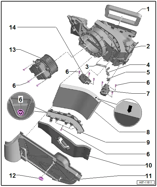
1 - Foam Seal
- For sealing the fresh air intake duct to the vehicle; bonded to the air intake duct
- Check for damage and if necessary replace. Refer to the Parts Catalog.
2 - Air Intake Housing
- With back pressure/fresh air and recirculation door
- Do not disassemble further
3 - Lever
- Refer to → Chapter "Overview - Actuators on Air Intake Housing".
- Apply a small amount of grease to the cam plate guides, the shaft bearings, the toothed segment as well as to the pins on the door levers. Refer to Parts Catalog.
4 - Fastener with Lever
- Removing and installing. Refer to → Chapter "Overview - Actuators on Air Intake Housing".
- Apply a small amount of grease to the cam plate guides, the shaft bearings, the toothed segment as well as to the pins on the door levers. Refer to Parts Catalog.
5 - Bracket
6 - Bolt
- 1 Nm
7 - Recirculation Door Motor -V113-
- Refer to → Chapter "Recirculation Door Motor -V113-, Removing and Installing"
8 - Dust and Pollen Filter
- Refer to → Chapter "Dust and Pollen Filter, Removing and Installing"
- Follow the replacement intervals. Refer to the Maintenance Tables.
- Different versions as replacement part (with and without activated charcoal filter insert): only dust and pollen filters with an activated charcoal filter insert are currently installed in the Audi Q7. Refer to the Parts Catalog and → Chapter "Dust and Pollen Filter with Activated Charcoal Insert, Element Information"
9 - Cover for Dust and Pollen Filter
- Removing and installing. Refer to → Chapter "Dust and Pollen Filter, Removing and Installing".
 Note
Note
Depending on the version, the cover housing may contain foam strips attached to it (for insulation in the room between the noise insulation. Refer to → Chapter "Dust and Pollen Filter, Removing and Installing".
10 - Insulation
- Removing and installing. Refer to → Chapter "Fresh Air Blower -V2- with Fresh Air Blower Control Module -J126-, Removing and Installing".
11 - Acoustic Cover
- Removing and installing. Refer to → Chapter "Dust and Pollen Filter, Removing and Installing".
12 - Screw Clips
- Removing and installing. Refer to → Chapter "Dust and Pollen Filter, Removing and Installing".
13 - Fresh Air Blower -V2- with Fresh Air Blower Control Module -J126-
- Refer to → Chapter "Fresh Air Blower -V2- with Fresh Air Blower Control Module -J126-, Removing and Installing"
- Check. Refer to Vehicle Diagnostic Tester in the "Guided Fault Finding" function
14 - Fresh Air Door Motor -V438-
- Refer to → Chapter "Fresh Air Door Motor -V438- Function, Removing and Installing"
Overview - Evaporator Housing
 Note
Note
- Currently the evaporator is delivered with the evaporator housing as a replacement part, for this reason do not disassemble the evaporator. If the evaporator is delivered later as a replacement part, then disassemble the evaporator housing. Refer to the Parts Catalog.
- For better illustration of the design of the evaporator housing, a disassembled evaporator housing is shown in the following figure.
- The evaporator housing with an evaporator as installed during production of the vehicle is currently completely preinstalled as a replacement part. Refer to the Parts Catalog.
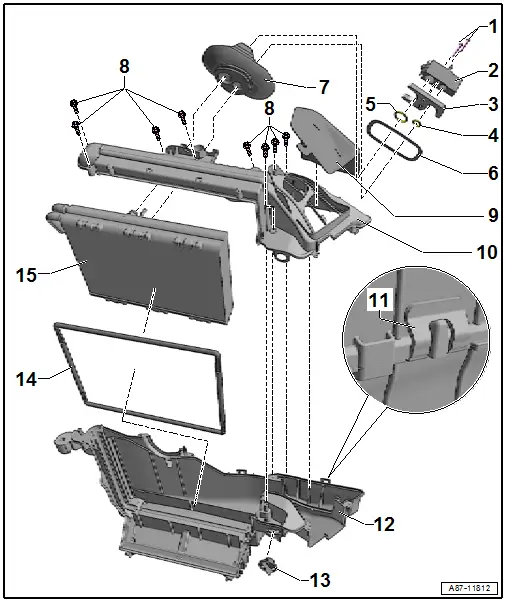
1 - Bolt
- 9 Nm
- Removing and installing. Refer to → Chapter "Front Expansion Valve, Removing and Installing".
2 - Expansion Valve
- Or removing and installing the refrigerant line from the expansion valve. Refer to → Chapter "Refrigerant Lines, Disconnecting from Front Expansion Valve and Reconnecting".
- Removing and installing. Refer to → Chapter "Front Expansion Valve, Removing and Installing".
3 - Retaining Pate
- Removing and installing. Refer to → Chapter "Evaporator in Front Heater and A/C Unit, Removing and Installing".
4 - O-Ring
- Replacing. Refer to → Chapter "Refrigerant Circuit Seals"
- Refer to the Parts Catalog for the allocation.
5 - O-Ring
- Replacing. Refer to → Chapter "Refrigerant Circuit Seals"
- Refer to the Parts Catalog for the allocation.
6 - Support Ring
- The support ring increases the pressure of the grommet on the plenum chamber rear wall. Refer to → Chapter "Refrigerant Lines, Disconnecting from Front Expansion Valve and Reconnecting".
- Check the seating of the support ring in the grommet. Refer to → Chapter "Refrigerant Lines, Disconnecting from Front Expansion Valve and Reconnecting".
7 - Grommet
- For sealing the opening through the plenum chamber rear wall for the refrigerant lines
- With support ring for sealing in the plenum chamber rear panel. Refer to → Chapter "Refrigerant Lines, Disconnecting from Front Expansion Valve and Reconnecting".
- Currently part of the replacement part "evaporator housing". Refer to the Parts Catalog.
8 - Bolt
- 1 Nm
9 - Insulation
- Installed between the air duct in the air distribution box and in the resonator chamber present in the air distribution box.
10 - Evaporator Housing Upper Section
11 - Retainer
- Open carefully
12 - Evaporator Housing Lower Section
- Both housing halves are held together via the bolts -item 8- and the catches -item 6-.
- Check for debris and if necessary clean before assembling both housing halves.
- Check the groove and spring connection to the evaporator housing upper section for damage.
 Note
Note
- Damaged or improperly joined connections can result in noises during operation.
- Fill (seal) small damages on the groove / spring connections carefully for example with a Silicone Adhesive -D 176 001 A3-. Refer to the Parts Catalog.
- The smallest leak on the groove / spring connection may cause whistling noise due to escaping air. Coat the connecting surfaces lightly with silicone grease (part number G 000 405 A2). Refer to the Parts Catalog.
13 - Cap
- for the connection to the glove compartment cooling
 Note
Note
Only installed on vehicles without the "glove compartment cooling" optional equipment installed. Refer to → Chapter "Air Guide for Glove Compartment Cooling, Removing and Installing".
14 - Seal
- Check for damage and the correct assembly on the evaporator.
15 - Evaporator
- Delivered as replacement evaporator part with various components needed for installation (evaporator housing, O-ring seals, expansion valve etc.). Refer to Parts Catalog
- Inspect the bonded foam seal for damage and that it is correctly bonded
- Removing and installing. Refer to → Chapter "Evaporator in Front Heater and A/C Unit, Removing and Installing". Removing from the heater and A/C unit Refer to → Chapter "Overview - Front Heater and A/C Unit")
