Audi Q7: Transmission, Installing
Special tools and workshop equipment required
- Torque Wrench 1332 Insert - Ring Wrench - 16mm -VAG1332/14-
- Clutch Module Transportation Lock -T40170-
- Engine Support -T10533/1-
- Cleaning Solution -D 009 401 04-
- Universal Adhesive - D 001 200 M2-
![]() Caution
Caution
This procedure contains mandatory replaceable parts. Refer to component overview prior to starting procedure.
Mandatory Replacement Parts
- Bolts - Torque converter
- Bolts - Engine/Transmission connecting
Procedure
![]() Note
Note
- Replace the bolts that were tightened with an additional turn.
- Replace the self-locking nuts and bolts, gaskets, seals and O-rings after removal,
- Secure all hose connections with hose clamps. Refer to the Parts Catalog.
- During installation, all cable ties must be installed at the same location.
Transmission Installation Tightening Specifications. Refer to → Chapter "Transmission Tightening Specifications".
- Before installing a replacement transmission, always clean out the ATF cooler and ATF lines using compressed air (maximum 10 bar (145 psi) ).
- Clean residue from the threaded holes in the cylinder block using a thread tap before installing.
- When installing a replacement transmission, install the transmission support, the transmission mounting and the tunnel crossmember on the new transmission. Refer to → Chapter "Overview - Subframe Mount".
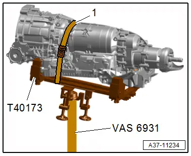
- Mount the transmission onto the Gearbox Support -T40173- and secure it using the tension strap -1- from the engine and transmission as shown.
![]() Caution
Caution
Installing the torque converter incorrectly can cause damage to the ATF pump drive plate.
Check the installed dimension of the torque converter. Refer to → Chapter "Torque Converter, Removing and Installing".
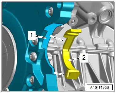
- The following preparations must be made before connecting the engine and transmission:
- Clean the contact surface -1- on the lower timing chain cover and on the locking piece -2- with Cleaning Solution -D 009 401 04-.
- Attach the locking piece with Universal Adhesive -D 001 200 M2- on the lower timing chain cover at the same time pay attention to the instruction manual.
![]() Note
Note
The installation position on a 3.0L TDI engine is shown.
- Bring the starter into the installation position.
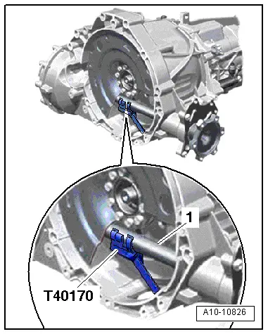
- Insert the Clutch Module Transportation Lock -T40170- in the transmission housing from below and secure it on the flange shaft -1-.
- Check if the alignment sleeves -A- for centering the engine/transmission are in the cylinder block and insert them if they are not.
- Inspect the aluminum bolts used to connect the engine to the transmission to see if they can be used again and mark them, if necessary.
![]() Note
Note
When bringing together the engine and transmission make sure that the locking piece is seated correctly.

Vehicles with a 3.0L TFSI Engine
![]() Note
Note
Replace the seals for the catalytic converters.
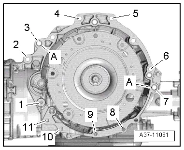
- Position the engine and transmission and install the bolts -4 and 5- and tighten to the final tightening specification.
- Remove the Engine Support -T10533/1-.
- Lift the transmission using the Engine and Gearbox Jack -VAS6931- and tighten the bolts for the tunnel crossmember. Refer to → Chapter "Overview - Subframe Mount".
- Position the Engine and Gearbox Jack -VAS6931- to the side and tighten the remaining bolts.
Vehicles with a 3.0L TDI Engine
- Place the engine on the transmission and at the same time install the bolt -1- for the starter.
- Tighten the bolts -2 through 11- by hand all the way.
- Tighten the bolts -1 through 11-.
- Remove the Tensioning Strap -T10038- and Engine Support Bridge - Special Hook (2 pc.) -10-222A/20-.
- Lift the transmission using the Engine and Gearbox Jack -VAS6931- and tighten the bolts for the tunnel crossmember. Refer to → Chapter "Overview - Subframe Mount".
- Move the Engine and Gearbox Jack -VAS6931- with the Gearbox Support -T40173- under the transmission.

All Vehicles
- Remove the Clutch Module Transportation Lock -T40170-.
![]() Note
Note
The following step is necessary to make sure the torque converter rests on the drive plate evenly and is not tilted.
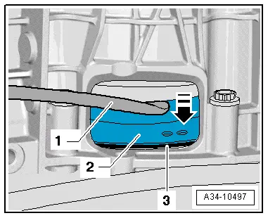
- Push the torque converter -2- slightly against the drive plate -3--arrow- using a pry bar -1-.
- Attach the torque converter to the drive plate as follows:
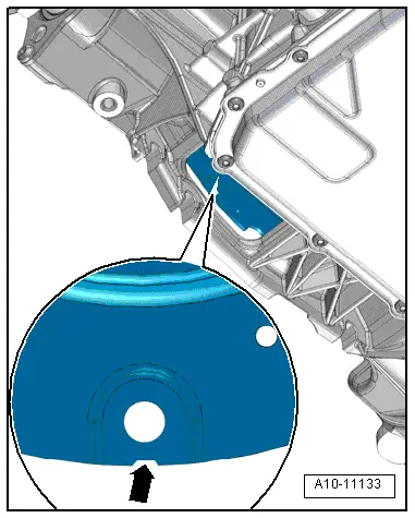
- Turn the torque converter so that hole next to the notch -arrow- is visible in the lower cut-out in the transmission housing as shown.
![]() Note
Note
There is only 1 notch on the circumference; rotate the torque converter as needed.
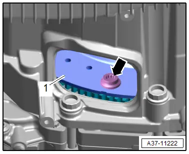
- In this position tighten the accessible bolt -arrow- for the torque converter -1--item 5-.
![]() Note
Note
Use the Torque Wrench 1332 Insert - Ring Wrench - 16mm -VAG1332/14- to tighten the bolts.
Vehicles with a 3.0L TFSI Engine
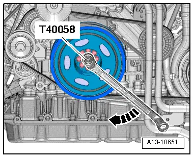
- Counterhold the crankshaft with the Crankshaft Socket -T40058- and an angled wrench and tighten the torque converter bolts.
![]() Note
Note
When mounting, turn the crankshaft only in the direction of engine rotation -arrow-.
Vehicles with a 3.0L TDI Engine
![]() Caution
Caution
Danger of camshaft timing chain skipping.
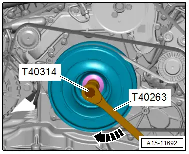
Turn the crankshaft only in the direction of engine rotation -arrow-.
- Counterhold the crankshaft to tighten the bolts for the torque converter with the Wrench - 21mm -T40263- and Adapter -T40314-.
All Vehicles
- Continue turning the crankshaft 60º and tighten the remaining five bolts -arrow- for the torque converter.
- Tighten the remaining engine/transmission connecting bolts.
Install in reverse order of removal. Note the following:
- Install the tower brace. Refer to → Suspension, Wheels, Steering; Rep. Gr.40; Suspension Strut and Upper Control Arm; Overview - Suspension Strut and Upper Control Arm.
- Install the parking lock emergency release cable. Refer to → Chapter "Front Parking Lock Emergency Release Cable, Removing and Installing".
- Install the ATF cooler. Refer to → Chapter "Overview - ATF Circuit".
- Install the drive axles. Refer to → Suspension, Wheels, Steering; Rep. Gr.40; Drive Axle; Overview - Drive Axle.
- Install the drive axle heat shield. Refer to → Suspension, Wheels, Steering; Rep. Gr.40; Drive Axle; Drive Axle Heat Shield, Removing and Installing.
- Install the catalytic converters. Refer to → Rep. Gr.26; Emissions Control System; Overview - Emissions Control System.
- Connections and routing. Refer to → Wiring diagrams, Troubleshooting & Component locations.
- Attach the steering intermediate shaft to the steering gear. Refer to → Suspension, Wheels, Steering; Rep. Gr.48; Steering Column; Steering Intermediate Shaft, Removing and Installing.
- Install the front exhaust pipe and align the exhaust system free of tension. Refer to → Rep. Gr.26; Emissions Control System; Overview - Emissions Control System.
- Install the front muffler and align the exhaust system free of tension. Refer to → Rep. Gr.26; Exhaust Pipes/Mufflers; Overview - Muffler.
- Install the Transmission Fluid Cooling Valve -N509-. Refer to → Rep. Gr.19; Coolant Pump/Coolant Thermostat; Overview - Electric Coolant Pump.
- Install the Coolant Recirculation Pump -V50-. Refer to → Rep. Gr.19; Coolant Pump/Coolant Thermostat; Overview - Electric Coolant Pump.
- Install the right coolant pipe on the transmission. Refer to → 6-Cylinder Direct Injection 3.0L 4V TFSI Supercharged Engine; Rep. Gr.19; Coolant Pipes; Coolant Pipes, Removing and Installing.
- Install the shield and subframe crossbrace. Refer to → Suspension, Wheels, Steering; Rep. Gr.40; Subframe; Overview - Subframe.
- Install the driveshaft. Refer to → Rear Final Drive 0D2, 0D3, 0DB; Rep. Gr.39; Driveshaft; Driveshaft, Removing and Installing.
- Fill with coolant. Refer to → Rep. Gr.19; Coolant System/Coolant; Coolant, Draining and Filling.
- Install the air filter housing. Refer to → Rep. Gr.23; Air Filter; Air Filter Housing, Removing and Installing or → Rep. Gr.24; Air Filter; Air Filter Housing, Removing and Installing.
- Follow all steps after connecting the battery. Refer to → Electrical Equipment; Rep. Gr.27; Battery; Battery, Disconnecting and Connecting.
![]() Caution
Caution
There is a risk of destroying control modules due to the excess voltage.
Do not use a charger to jump start.
- Check the parking lock emergency release. Refer to → Chapter "Emergency Release from P".
- Check the ATF level and correct if necessary. Refer to → Chapter "ATF Level, Checking".

Transmission Tightening Specifications
![]() Note
Note
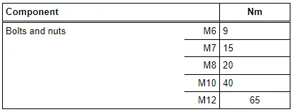
- The tightening specifications apply only to lightly greased, oiled, phosphated or blackened nuts and bolts.
- Additional lubricant such as engine oil or transmission fluid may be used, but do not use lubricant containing graphite.
- Do not use any ungreased parts.
- Tightening specification tolerance: +- 15%.
Other tightening specifications:
Torque Converter -item 5-
Fastening the Transmission to the 6-Cylinder Engine

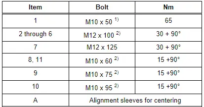
1) Attaches the starter to the transmission. Bolt strength rating 10.9. There is no limit to the number of times the steel bolt can be used again.
2) Aluminum bolts may be used two times.
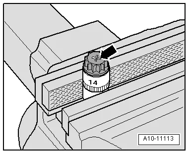
- The aluminum bolts may be used two times. Therefore, the bolts must be marked with two notches "X" made by a chisel after they have be used the first time -arrow-.
- To prevent damaging the bolts when marking them, do not clamp them in a vise. Insert the bolt in a 14 mm socket with a 1/2 drive, which is inserted in to the vise, as shown.
- Bolts marked with an "X" may not be used again.