Audi Q7: Transmission, Removing
Transmission, Removing, Vehicles with 3.0L TFSI Engine
Special tools and workshop equipment required
- Engine and Gearbox Jack -VAS6931-
- Engine Support -T10533/1-
- Engine Support -T10533-
- Crankshaft Socket -T40058-
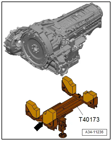
- Gearbox Support -T40173-
- Commercially available step ladder
- M10x40 collar bolt
- M10 nut
![]() Caution
Caution
This procedure contains mandatory replaceable parts. Refer to component overview prior to starting procedure.
Mandatory Replacement Parts
- Bolts - Torque converter
- Bolts - Engine/Transmission connecting
Preparing the Gearbox Support -T40173-:
- The bracket -arrow- must be turned so that the longer side faces upward, as shown.
Removing
- Position the front wheels so they are straight.
![]() Caution
Caution
Risk of destroying electronic components when disconnecting the battery.
Follow the steps when disconnecting the battery.
- Disconnect the battery. Refer to → Electrical Equipment; Rep. Gr.27; Battery; Battery, Disconnecting and Connecting.
- Remove the air filter housing. Refer to → Rep. Gr.24; Air Filter; Air Filter Housing, Removing and Installing
- Remove the noise insulations. Refer to → Body Exterior; Rep. Gr.66; Noise Insulation; Noise Insulation, Removing and Installing.
- Drain the coolant. Refer to → Rep. Gr.19; Coolant System/Coolant; Coolant, Draining and Filling.
- Remove the driveshaft. Refer to → Rear Final Drive 0D2, 0D3, 0DB; Rep. Gr.39; Driveshaft; Driveshaft, Removing and Installing.
- Remove the subframe crossbrace. Refer to → Suspension, Wheels, Steering; Rep. Gr.40; Subframe; Subframe Crossbrace, Removing and Installing.
- Remove the right coolant pipe on the transmission. Refer to → 6-Cylinder Direct Injection 3.0L 4V TFSI Supercharged Engine; Rep. Gr.19; Coolant Pipes; Coolant Pipes, Removing and Installing
- Remove the Coolant Recirculation Pump -V50- with the bracket. Refer to → Rep. Gr.19; Coolant Pump/Coolant Thermostat; Electric Coolant Pump, Removing and Installing.
- Remove the Transmission Fluid Cooling Valve -N509-. Refer to → Rep. Gr.19; Coolant Pump/Coolant Thermostat; Coolant Valves, Removing and Installing.
- Remove the front muffler. Refer to → Rep. Gr.26; Exhaust Pipes/Mufflers; Front Muffler, Removing and Installing.
- Remove the steering intermediate shaft from the steering gear and the push the splines together. Refer to → Suspension, Wheels, Steering; Rep. Gr.48; Steering Column; Steering Intermediate Shaft, Removing and Installing.
- Remove the left subframe shield. Refer to → Suspension, Wheels, Steering; Rep. Gr.40; Subframe; Subframe Crossbrace, Removing and Installing.
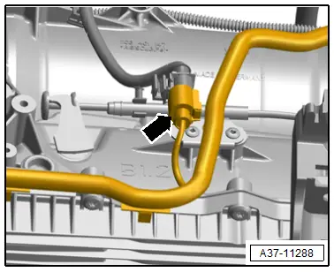
- Disconnect the connector -arrow-.
![]() Caution
Caution
There is a risk of destroying the transmission control module (Mechatronic) with static discharge.
Do not touch connector terminals in the transmission connector with hands.
- To discharge static electricity, touch the transmission housing (without wearing gloves).
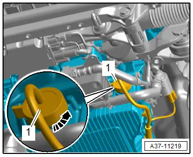
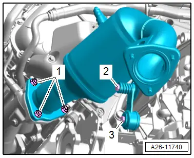
- Turn the twist lock counter-clockwise in direction of -arrow- and disconnect the connector -1- from the transmission.
- Free up the wiring harness on the transmission.
- Remove the bolts -2 and 3- and remove the mounting for the left catalytic converter.
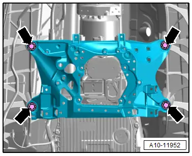
- Loosen the nuts -1- several turns but do not remove.
- Repeat the procedure on the opposite side of the vehicle.
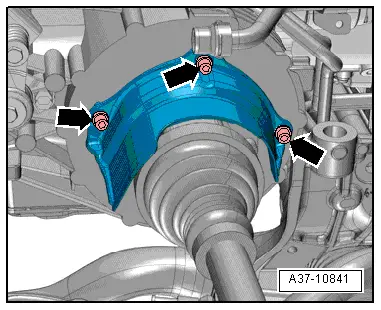
- Remove the bolts -arrows- and remove the heat shield from the right drive axle.
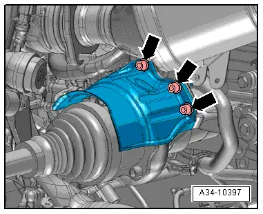
- Remove the bolts -arrows- and the left drive axle heat shield.
- Remove the right and left drive axles from the transmission. Refer to → Suspension, Wheels, Steering; Rep. Gr.40; Drive Axle; Drive Axle, Removing and Installing.
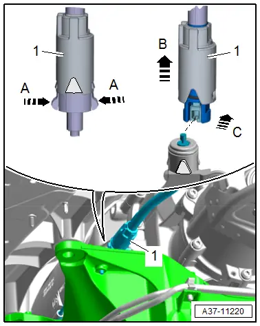
- Release the retainers in the direction of -arrows A- and slide the sleeve -1- on the emergency release cable in the direction of -arrow B-.
- Disengage the rear emergency release cable from the front emergency release cable -arrow C-.
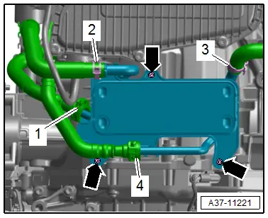
- Remove the bolts -arrows- and push the ATF cooler with the hoses -1, 2, and 4- connected to the side.
![]() Note
Note
Ignore item -3-.
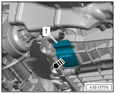
- Remove the lower cover -1- from the transmission in direction of -arrow-.
- Counterhold the crankshaft with the Crankshaft Socket -T40058- and an offset open-end wrench and loosen the torque converter bolts.
![]() Note
Note
When mounting, turn the crankshaft only in the direction of engine rotation -arrow-.
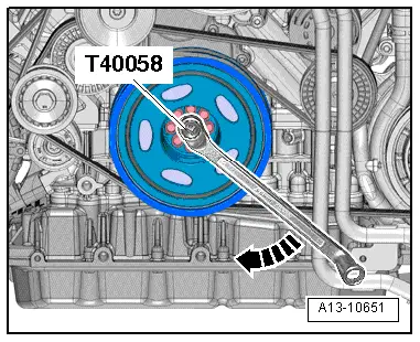
- Remove the six bolts -arrow- for the torque converter from the drive plate -1-. To do so turn the crankshaft respectively a 60º additional turn in the direction of engine rotation.

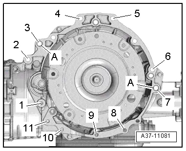
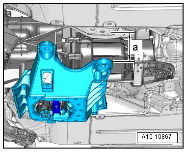
- Remove the engine/transmission connecting bolts -1, 2, and 3- and -6 to 11-.
![]() Note
Note
Ignore item -A-.

![]() Caution
Caution
Danger of leaks in the ATF pan.
The Gearbox Support -T40173- must not be set on the ATF pan.
- Place the Gearbox Support -T40173- on the Engine and Gearbox Jack -VAS6931- with the mounting blocks -1 and 2- under the transmission as shown.
- Mount the front bracket on the left transmission side behind the opening for the torque converter on the transmission housing.
- Place on the right transmission side on the front mounting block on the front final drive.
- Secure transmission with the tensioning strap -1- from the engine and transmission.
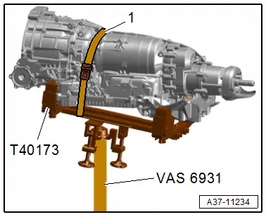
![]() Note
Note
The Gearbox Support -T40173- is not illustrated.
- Remove the bolts from the tunnel crossmember -arrows-.
- Lower the tunnel crossmember to the dimension -a- using the Engine and Gearbox Jack -VAS6931-.
- Dimension -a- = maximum 55 mm.
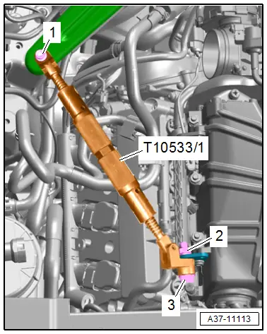
- Secure the engine against tipping, to do so tighten the Engine Support -T10533/1- with the bolts -1 and 3- and the nut -2-, as shown.
- Remove the last engine/transmission connecting bolts -4 and 5-.
- Separate the transmission from the engine.
- Carefully lower the transmission with the Engine and Gearbox Jack -VAS6931- at the same time pay attention to the clearance to the catalytic converter. If required, change the angle of the engine with the Engine Support -T10533/1-.