Audi Q7: TV System
General Information - TV System
The TV system is part of the MMI Infotainment system.
TV Tuner -R78- is connected via the MOST-Bus to the other components of the MMI Infotainment system. Operation is performed via the Multimedia System Control Head -E380-.
A DVD Changer -R161- (6G0) is located in the luggage compartment on the left.
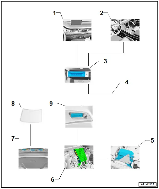
1 - Front Information Display Control Head -J685- in center of the instrument panel
2 - Multimedia System Control Head -E380- in the center console
3 - Information Electronics Control Module 1 -J794- in the glove compartment
4 - MOST Bus
5 - Digital Soand System Control Module -J525- in the luggage compartment
6 - TV Tuner -R78- in luggage compartment on rear right side
7 - Antenna amplifier inside the rear lid
8 - Rear Window Antennas
9 - DVD Changer -R161- in the luggage compartment on the left rear side
Fault Finding is performed using the "Guided Fault Finding". Refer to Vehicle Diagnostic Tester.
Antenna wires, repairing. Refer to → Electrical Equipment; Rep. Gr.97; Antenna Wires, Repairing.
Notes on MOST Bus
The optical Data Bus "MOST Bus" is used in addition to the CAN Bus.
A fiber-optic cable is used. Fiber optic cables are routed inside corrugated tubes for protection.
Replace the complete fiber optic cable if possible.
The front surface of the connectors must not be contaminated.
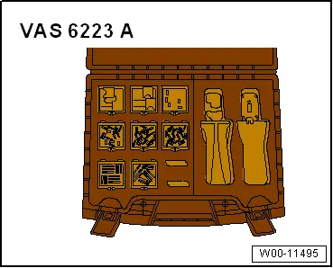
If disconnecting the connectors: Attach the Fiber-Optic Repair Set - Connector Protective Caps -VAS6223/9-.
When routing fiber optic cables, make sure not to go below the minimum bending radius of 25 mm. Do not crush or kink the fiber optic cables.
Repairing fiber optic cables. Refer to → Electrical Equipment; Rep. Gr.97; Fiber-Optic Cable.
Component Location Overview - TV System
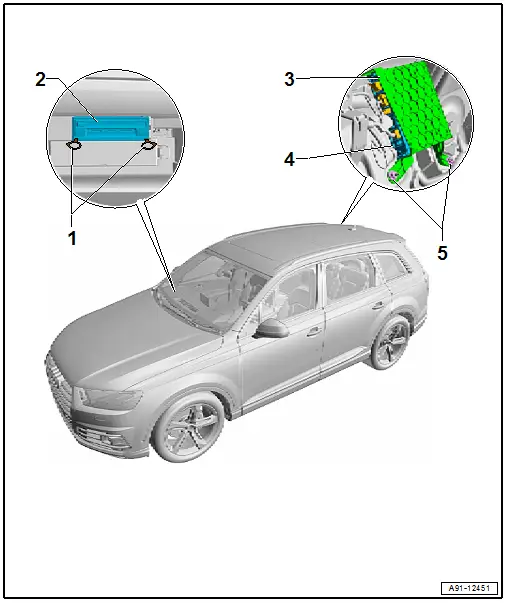
1 - Radio Removal Tool -T10057-
2 - Information Electronics Control Module 1 -J794-
- Connector Assignment. Refer to → Wiring diagrams, Troubleshooting & Component locations.
- Removing and Installing. Refer to → Chapter "Information Electronics Control Module 1 -J794-, Removing and Installing".
3 - Bracket
4 - TV Tuner -R78-
- Connector Assignment. Refer to → Wiring diagrams, Troubleshooting & Component locations.
- Removing and Installing. Refer to → Chapter "TV Tuner, Removing and Installing".
5 - Nut
- 3 Nm
- Quantity: 2
TV Tuner, Removing and Installing
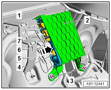
The TV Tuner - R78- is located behind the right luggage compartment side trim panel.
Special tools and workshop equipment required
- Fiber-Optic Repair Set - Connector Protective Caps -VAS6223/9-.
 Note
Note
If replacing the control module, select the "Replace control module" function for the corresponding control module. Refer to Vehicle Diagnostic Tester.
Removing
- Turn off the ignition and all electrical equipment and remove the ignition key.
- Remove the right luggage compartment side trim panel. Refer to → Body Interior; Rep. Gr.70; Luggage Compartment Trim Panels; Luggage Compartment Side Trim Panel, Removing and Installing.
- Release and disconnect the connectors -4 through 7- on the TV Tuner - R78--1-.

- Insert the Fiber-Optic Repair Set - Connector Protective Caps -VAS6223/9--1- onto the MOST Busconnector -2-.
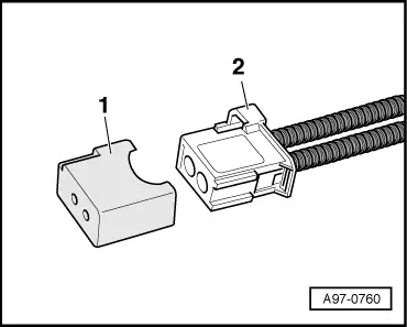
The TV Tuner -R78--1- is only clipped into the bracket -2-.
- Push the tab in direction of -arrow- and pull the TV Tuner -R78--1- out of the bracket -2-.
To remove the bracket -2- remove the nuts -3-.
Installing
- Install in reverse order of removal.
Tightening Specifications
- Refer to → Chapter "Component Location Overview - TV System"

