Audi Q7: Upper Control Arm, Removing and Installing
Special tools and workshop equipment required
- Vehicle Diagnostic Tester
- Torque Wrench 1331 5-50Nm -VAG1331-
- Torque Wrench 1331 Insert - Ring Wrench - 16mm -VAG1331/12-, not illustrated
- Torque Wrench 1332 40-200Nm -VAG1332-
- Engine and Gearbox Jack -VAS6931-
- Engine/Gearbox Jack Adapter - Wheel Hub Support -T10149-
Removing
Before starting work:
- Versions with coil springs: determine the curb weight position.. Refer to → Chapter "Wheel Bearing in Curb Weight Position, Lifting Vehicles with Coil Spring".
- Versions with air suspension: determine the standard vehicle height. Refer to → Chapter "Wheel Bearing at Standard Vehicle Height, Lifting Vehicles with Air Suspension".
- Remove the front wheel. Refer to → Chapter "Wheels and Tires".
- Turn the wheel hub, until the wheel bolt hole is on top.
 Caution
Risk of destroying the wheel bearing when installing the wheel bolt.
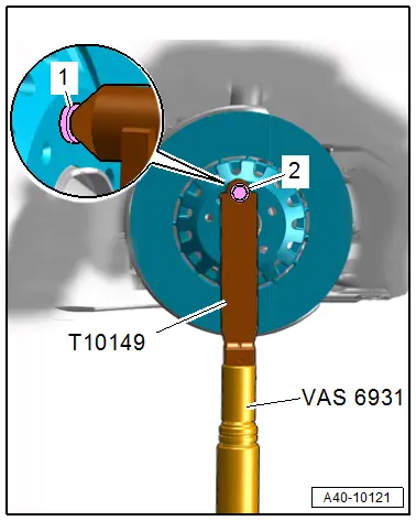
So that the installed wheel bolt cannot push against the wheel bearing, it (the bolt) must be installed with a washer inserted in between.
- Install the Engine/Gearbox Jack Adapter - Wheel Hub Support -T10149- with a wheel bolt -2- and inserted washer -1- on the wheel hub.
- Support the wheel bearing housing over the Engine/Gearbox Jack Adapter - Wheel Hub Support -T10149- using the Engine and Gearbox Jack -VAS6931-.
 WARNING
Risk of accident!
- Do not lift or lower the vehicle when the Engine and Gearbox Jack -VAS6931- is under the vehicle.
- Do not leave the Engine and Gearbox Jack -VAS6931- under the vehicle any longer than necessary.
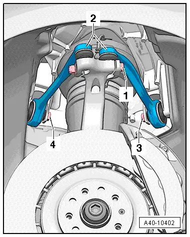
- Loosen the threaded connection -1-.
 Caution
There is a risk of damaging the wheel bearing housing.
The slits in the wheel bearing housing must not be widened using a chisel or similar tool!
- Remove the corresponding joint pins in the upper control arm -2- from the wheel bearing housing.
 Note
Note
Do not lower wheel bearing housing more than necessary.
- Remove the bolt -4 or 3- and remove the corresponding control arm upward.
Installing
Install in reverse order of removal and note the following:
- Install the threaded connections for the components with bonded rubber bushings only until stop but do not yet tighten.
 Note
Note
Bonded rubber bushings have a limited range of motion. Only tighten suspension bolts when vehicle is in curb weight position or at standard vehicle height.
- Lifting the wheel bearing in curb weight position (refer to → Chapter "Wheel Bearing in Curb Weight Position, Lifting Vehicles with Coil Spring") or at standard vehicle height (refer to → Chapter "Wheel Bearing at Standard Vehicle Height, Lifting Vehicles with Air Suspension").
Tightening Specifications
- Refer to → Chapter "Overview - Suspension Strut and Upper Control Arm"
- Refer to → Chapter "Wheels and Tires"
Upper Control Arm Bearing, Replacing
Special tools and workshop equipment required
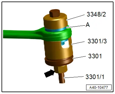
- Subframe Bushing Tool Kit -3301-
- Bearing Installer - Multiple Use -3348-
Procedure
- The upper control arm us removed. Refer to → Chapter "Upper Control Arm, Removing and Installing"
- Mark the press-in depth of the bonded rubber bushing for example using a waterproof felt-tip pen.
Pull out Bonded Rubber Bushing
- Clamp the control arm in a vise with protective covers.
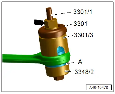
- Mount the special tools as shown.
- Remove the bonded rubber bushing -A- by turning the nut -arrow-.
Installing the Bonded Rubber Bushing
 Note
Note
Do not use lubricant!
- Transfer the marking for the press-in depth from the old bonded rubber bushing to the new one.
- Mount the special tools as shown.
- Install the bonded rubber bushing -A- by turning the nut -arrow-, at the same time to the press-in depth markings made previously.
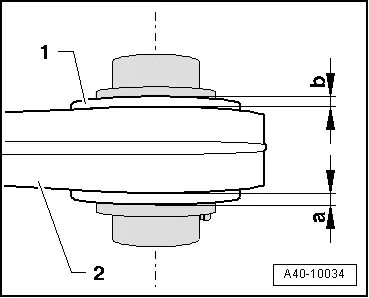
- Check the press-in depth for the bonded rubber bushing -1- inside the control arm -2-.
- Specified value: dimension -a- = dimension -b-.
- When the dimensions are different, tighten the bonded rubber bushings.