Audi Q7: Overview - Lower Control Arm and Ball Joint
Audi Q7 (4M) 2016-2026 Workshop Manual / Chassis / Suspension, Wheels, Steering / Front Suspension / Overview - Lower Control Arm and Ball Joint
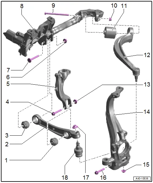
1 - Wheel Bearing Housing Side Bonded Rubber Bushing
- Replacing. Refer to → Chapter "Control Arm Ball Bearing, Replacing, Wheel Bearing Housing Side".
2 - Control Arm
- Removing and installing. Refer to → Chapter "Control Arm, Removing and Installing".
3 - Subframe Side Bonded Rubber Bushing
- Replacing. Refer to → Chapter "Control Arm Ball Bearing, Replacing, Subframe Side".
4 - Bolt
- Replace after removing
5 - Shock Absorber Fork
- Removing and installing. Refer to → Chapter "Shock Absorber Fork, Removing and Installing".
6 - Nut
- 70 Nm +180º
- Replace after removing
- Tighten either in the curb weight position (refer to → Chapter "Wheel Bearing in Curb Weight Position, Lifting Vehicles with Coil Spring") or at the standard vehicle height (refer to → Chapter "Wheel Bearing at Standard Vehicle Height, Lifting Vehicles with Air Suspension").
7 - Bolt
- Replace after removing
8 - Subframe
9 - Bolt
- Replace after removing
10 - Nut
- 70 Nm +180º
- Replace after removing
- Tighten either in the curb weight position (refer to → Chapter "Wheel Bearing in Curb Weight Position, Lifting Vehicles with Coil Spring") or at the standard vehicle height (refer to → Chapter "Wheel Bearing at Standard Vehicle Height, Lifting Vehicles with Air Suspension").
11 - Bonded Rubber Bushing
- Replacing. Refer to → Chapter "Guide Link Bonded Rubber Bushing, Removing and Installing".
12 - Guide Link
- Removing and installing. Refer to → Chapter "Guide Link, Removing and Installing".
13 - Nut
- 90 Nm +90º
- Replace after removing
- Tighten either in the curb weight position (refer to → Chapter "Wheel Bearing in Curb Weight Position, Lifting Vehicles with Coil Spring") or at the standard vehicle height (refer to → Chapter "Wheel Bearing at Standard Vehicle Height, Lifting Vehicles with Air Suspension").
14 - Wheel Bearing Housing
15 - Nut
- 140 Nm
- Replace after removing
- When reusing the guide link clean the pin threads from the remaining locking compound residue
16 - Bolt
- 40 Nm
- Replace after removing
17 - Nut
- Replace after removing
- 120 Nm
- When reusing the ball joint clean the pin threads from the remaining locking compound residue
18 - Ball Joint
- Removing and installing. Refer to → Chapter "Ball Joint, Removing and Installing".

