Audi Q7: Wheel Housing Liner
Overview - Front Wheel Housing Liner
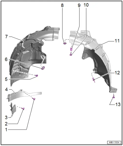
1 - Bolt
- 2.5 Nm
- Quantity: 2
2 - Bolt
- 2.5 Nm
- Quantity: 2
3 - Front Outer Wheel Spoiler
- Removing and Installing. Refer to → Chapter "Front Wheel Spoiler, Removing and Installing, Outer".
4 - Inner Front Wheel Spoiler
- Removing and Installing. Refer to → Chapter "Front Wheel Spoiler, Removing and Installing, Inner".
5 - Bolt
- 2.5 Nm
- Quantity: 3
6 - Nut
- Quantity: 3
- 2.5 Nm
7 - Front Wheel Housing Liner Front Section
- Removing and Installing. Refer to → Chapter "Front Wheel Housing Liner, Removing and Installing, Front Section".
8 - Nut
- 2.5 Nm
- Quantity: 5
9 - Bracket
- For the wheel housing liner to the fender
10 - Bolt
- 2.5 Nm
11 - Front Wheel Housing Liner Rear Section
- Removing and Installing. Refer to → Chapter "Front Wheel Housing Liner, Removing and Installing, Rear Section".
12 - Expanding Rivet
- Quantity: 2
13 - Bolt
- 2.5 Nm
- Quantity: 3
Overview - Rear Wheel Housing Liner
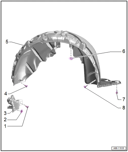
1 - Bolt
- 2.5 Nm
2 - Nut
- 2.5 Nm
- Quantity: 2
3 - Rear Wheel Spoiler
- Removing and Installing. Refer to → Chapter "Rear Wheel Spoiler, Removing and Installing".
4 - Bolt
- 2.5 Nm
- Quantity: 4
5 - Rear Wheel Housing Liner
- Removing and Installing. Refer to → Chapter "Rear Wheel Housing Liner, Removing and Installing".
6 - Nut
- 2.5 Nm
- There are different numbers
- Left: quantity 5
- Right: quantity 4
7 - Bolt
- 2.5 Nm
- Quantity: 2
8 - Bolt
- 2.5 Nm
- Quantity: 5
Front Wheel Housing Liner, Removing and Installing
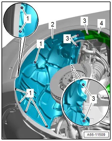
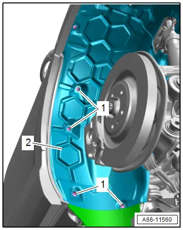
Front Wheel Housing Liner, Removing and Installing, Front Section
Removing
- Remove the nuts -3- and bolts -1-.
- Remove the wheel housing liner front section -2-.
Installing
Install in reverse order of removal and note the following:
- The wheel housing liner front section must be pushed behind the wheel housing liner rear section -4-.
Tightening Specifications
- Refer to → Chapter "Overview - Front Wheel Housing Liner"
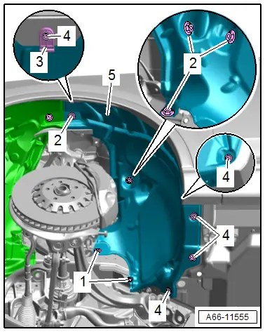
Front Wheel Housing Liner, Removing and Installing, Rear Section
Removing
- Remove the expanding rivets -1-.
- Remove the nuts -2- and bolts -4-.
- Disengage the bracket -3- from the fender.
- Remove the wheel housing liner -5-.
Installing
Install in reverse order of removal.
Tightening Specifications
- Refer to → Chapter "Overview - Front Wheel Housing Liner"
Front Wheel Spoiler, Removing and Installing
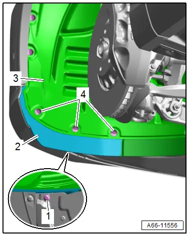
Front Wheel Spoiler, Removing and Installing, Outer
Removing
- Remove the bolt -1-.
- Remove the screws -4- and the front section of the front wheel housing liner -3- at the bottom.
- Remove the wheel spoiler -2-.
Installing
Install in reverse order of removal.
Tightening Specifications
- Refer to → Chapter "Overview - Front Wheel Housing Liner"
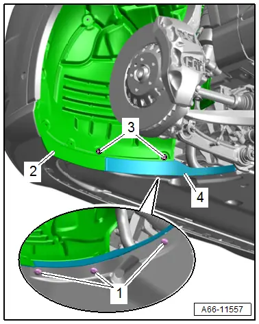
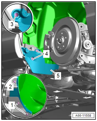
Front Wheel Spoiler, Removing and Installing, Inner
Removing
- Remove the bolt -1-.
- Remove the screws -3- and the front section of the front wheel housing liner -2- at the bottom.
- Remove the wheel spoiler -4-.
Installing
Install in reverse order of removal.
Tightening Specifications
- Refer to → Chapter "Overview - Front Wheel Housing Liner"
Rear Wheel Housing Liner, Removing and Installing
Removing
- Remove the nuts -2- and bolts -1-.
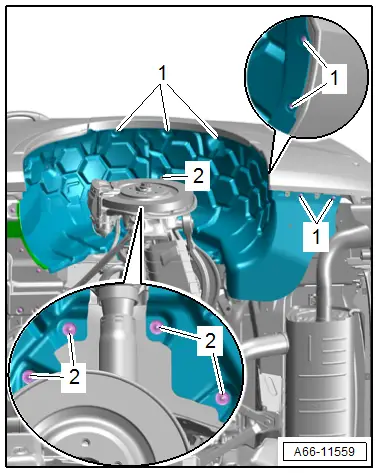
- Remove the bolts -1-.
- Remove the wheel housing liner -2-.
Installing
Install in reverse order of removal.
Tightening Specifications
- Refer to → Chapter "Overview - Rear Wheel Housing Liner"
Rear Wheel Spoiler, Removing and Installing
Removing
- Loosen the rear wheel housing liner at the front and press it to the side. Refer to → Chapter "Rear Wheel Housing Liner, Removing and Installing".
- Remove the bolts -1, 2, and 3-.
- Remove the nuts -4- and lift the bottom of the wheel housing liner.
- Remove the wheel spoiler -5-.
Installing
Install in reverse order of removal.
Tightening Specifications
- Refer to → Chapter "Overview - Rear Wheel Housing Liner"

