Audi Q7: Airbag Adapter, Connecting and Disconnecting
Special tools and workshop equipment required
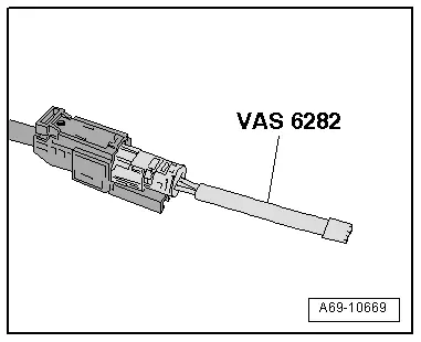
- Airbag Lockout Adapter -VAS6282-
Disconnecting the Airbag Connector
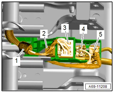
- Unclip the cable holder -1-.
 WARNING
- Follow all safety precautions when working on pyrotechnic components. Refer to → Chapter "Safety Precautions for Pyrotechnic Components".
- Before handling pyrotechnic components (for example, disconnecting the connector), the person handling it must "discharge static electricity". This can be done by briefly touching the door striker pin, for example.
- Disconnect the connector -2- for the thorax airbag from the connector station by releasing the tabs.
3 - For versions with seat heating
4 - For seat belt latch, outer seat
5 - For seat belt latch, center seat
- Connect the -VAS6282- to the thorax airbag connector.
 Caution
The -VAS6282- must stay connected to seat until the seat is installed again.
 Note
Note
Ensure the airbag adapter engages correctly.
Connecting the Airbag Connector
 WARNING
- Follow all safety precautions when working on pyrotechnic components. Refer to → Chapter "Safety Precautions for Pyrotechnic Components".
- Before handling pyrotechnic components (for example, connecting the connector), the person handling it must "discharge static electricity". This can be done by briefly touching the door striker pin, for example.
Connecting the airbag connectors happens in reverse order, noting the following:
 Note
Note
Make sure the connectors are pushed in all the way and that they engage audibly.
 WARNING
Repairing pyrotechnic components (for example the airbag and seat belt tensioner) incorrectly increases the risk of unintentional deployments when the battery is connected.
- The ignition must be on when connecting the battery.
- For personal safety when connecting the battery, stay out of the deployment area of the airbag and maintain a distance from the seat belt tensioners/seat belts.
- Make sure that there are no other people inside the vehicle at the time when the battery is connected.
- Connect the battery ground cable with the ignition turned on. Refer to → Electrical Equipment; Rep. Gr.27; Battery; Battery, Disconnecting and Connecting.
 Note
Note
If the Airbag Indicator Lamp -K75- indicates a fault, check the Diagnostic Trouble Code (DTC) memory, erase it and check it again using the Vehicle Diagnostic Tester.
Modular Wiring Routing, Disconnecting and Connecting
Special tools and workshop equipment required
- Engine/Transmission Holder - Seat Repair Fixture -VAS6136-
Individual Wire, Removing
 WARNING
- Follow all safety precautions when working on pyrotechnic components. Refer to → Chapter "Safety Precautions for Pyrotechnic Components".
- Before handling pyrotechnic components (for example, disconnecting the connector), the person handling it must "discharge static electricity". For example, this can be done by briefly touching the door striker.
- Remove the seat. Refer to → Chapter "Bench Seat/Single Seat, Removing and Installing".
- Secure the seat on the -VAS6136-. Refer to → Chapter "Front Seat, Mounting on Fixture for Seat Repair".
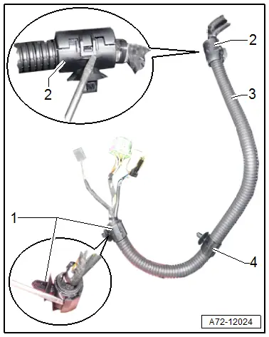
- Open the front cable holder -1- using a screwdriver.
- Open the rear cable holder -2- for the wire routing on the seat pan using a screwdriver to release the hook -2-.
- Remove the cable holder from the corrugated tube -3-.
- Disconnect the halves of the corrugated tube.
- Cut the cable tie if necessary to remove a single wire.
 Note
Note
Replacing a faulty wire or thorax airbag. Refer to → Electrical Equipment General Information; Rep. Gr.97; Wiring Harness and Connector Repair; Wiring Harnesses, Repairing or → Chapter "Rear Thorax Airbag Wire, Removing and Installing".
- Cut through the cable tie and remove the individual wire.
Individual Wire, Installing
 WARNING
- Follow all safety precautions when working on pyrotechnic components. Refer to → Chapter "Safety Precautions for Pyrotechnic Components".
- Before handling pyrotechnic components (for example, connecting a connector), the person handling it must "discharge static electricity". For example, this can be done by briefly touching the door striker.
- Follow all the instructions when installing the front seat. Refer to → Chapter "Front Seat, Removing and Installing".
Install in reverse order of removal and note the following:
- When bundling and placing individual wires, make sure the wires are not twisted.
 Note
Note
- During installation, all cable ties, cable holders and clips must be installed at the same location.
- Make sure the connectors are pushed in all the way and that they engage audibly.
Installation instructions: for example tightening specifications, replacing components. Refer to → Chapter "Overview - Bench Seat/Single Seat".

