Audi Q7: Axle Alignment Procedure
 Note
Note
Determine the correct suspension version. Refer to → Chapter "Production Control Number (PR Number) Explanations".
- A vehicle with coil springs can only be measured at curb weight position. Refer to → Chapter "Standard Vehicle Height for Axle Alignment on Vehicles with Air Suspension, Checking".
- A vehicle with air suspension can only be measured in the "axle alignment" mode.
- Connect the Vehicle Diagnostic Tester.
- Switch the ignition on.
- Select and start the Diagnostic operating mode.
- Select the Test plan tab.
- Select the button Individual tests and select the following tree structures one after the other:
- Suspension
- Suspension control
- 01 - OBD-capable systems
- 74 - Drivetrain Control Module J775
- 74 - Drivetrain Control Module Functions
- 74 - Complete basic setting
- Start the selected program and follow the instructions in the display of the Vehicle Diagnostic Tester.
Observe the following work sequence!
1 - Perform wheel run-out compensation. Refer to → Chapter "Wheel Run-Out Compensation".
2 - Check the maximum steering angle. Refer to → Chapter "Maximum Steering Angle, Checking".
3 - Check the rear axle steering gear orientation. Refer to → Chapter "Rear Axle Steering Gear Orientation, Checking".
4 - Check the rear axle camber and adjust if necessary. Refer to → Chapter "Rear Axle Camber, Adjusting".
5 - Check rear axle toe and adjust if necessary. Refer to → Chapter "Rear Axle Toe, Adjusting".
6 - Check front axle camber and adjust if necessary. Refer to → Chapter "Front Axle Camber, Centering".
7 - Check the front axle toe and adjust if necessary. Refer to → Chapter "Front Axle Toe, Adjusting".
If the standard vehicle height is readapted. Refer to → Chapter "Standard Vehicle Height, Readapting".
When the adjustment on the suspension is changed:
- Calibrate the Steering Angle Sensor -G85- using the Vehicle Diagnostic Tester. Refer to → Chapter "Steering Angle Sensor -G85- Basic Setting".
- Adjust the headlamps. Refer to → Electrical Equipment; Rep. Gr.94; Headlamps; Headlamp, Adjusting.
If the adjustment on the rear axle is changed:
- Adjust the adaptive cruise control. Refer to → Chapter "Adaptive Cruise Control (ACC), Adjusting".
- Driver Assistance Systems Front Camera, Calibrating. Refer to → Chapter "Driver Assistance Systems Front Camera, Calibrating".
- Infrared System, Calibrating. Refer to → Chapter "Infrared System, Calibrating".
- Calibrate the rearview camera system. Refer to → Communication; Rep. Gr.91; Rearview Camera System; Rearview Camera System, Calibrating.
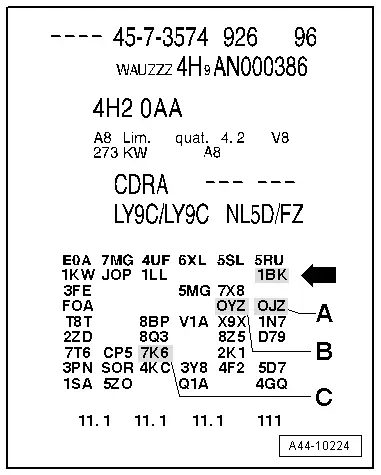
Production Control Number (PR Number) Explanations
Vehicle Data Label
The PR number on the vehicle data label indicates which suspension is equipped.
Example of a vehicle data label:
- 1BK -arrow- = PR Number standard suspension air suspension
 Note
Note
Component location in the vehicle data label.
ELSA/Vehicle-Specific Notes
The relevant information regarding the suspension, spring/shock absorber combinations and the driver assistance systems are in ELSA in the Specific Vehicle Information in the "Vehicle Data" document.
Wheel Run-Out Compensation
A correct toe-in adjustment will not be possible without performing lateral run-out compensation!
The lateral run-out of the wheel must be compensated for. Otherwise, measurement will result in false readings.
Permissible axial run-out of the wheel rims can exceed the specified toe setting tolerance. If compensation for wheel run-out is not performed, it will not be possible to obtain a correct toe-in adjustment.
Follow the operating instructions provided by the manufacturer of the alignment equipment.
The vehicle is equipped with an electronically controlled 8-speed automatic transmission. For this reason pay attention to the following for the wheel run-out compensation: if the engine is switched off in the selector lever position N, the transmission remains in N for approximately 30 minutes, then it automatically engages P. As soon as the driver door was opened, P was directly engaged. Refer to the Owner's Manual.
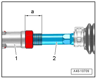
Maximum Steering Angle, Checking
The wheel alignment computer determines the maximum steering angle.
- If the maximum steering angle was determined on the alignment tester and the value is not within the tolerance, then check for damage or deformations to the steering and suspension components and evaluate the tie rod symmetry. In this case, shorten the "longer" tie rod end (install it deeper into the tie rod) and replace any damaged components.
- If a steering wheel fault is determined on the alignment equipment when setting the center position of the steering, then check the steering and suspension for damage or deformations and replace any damaged components. Check the tie rod symmetry as well.
- Measure dimension -a- on the "shorter" tie rod head. Shorten the "longer" tie rod head to the same dimension. To do this, install the tie rod head -1- deeper on the tie rod -2-.
- Specified value: dimension -a- right tie rod end = dimension -a- left tie rod end.
- The maximum permissible difference between the right and left greater than 2.5 mm.
- When the steering wheel returns to its center position, let the steering wheel "come to its center" using even movements.
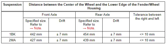
Vehicles with Coil Springs, Checking the Curb Weight Position for Axle Alignment
Before beginning and axle alignment on vehicles with coil springs the curb weight position must be checked. Explanation of the curb weight position.
Determine the Dimension -a-.
- Determine dimension -a- between the center of the wheel and the lower edge of the fender/wheel housing as illustrated.
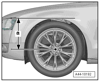
Overview of Dimension -a-
 Note
Note
When the curb weight position is not OK then a correct axle alignment cannot be performed.
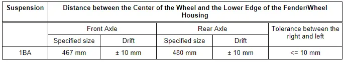
Standard Vehicle Height for Axle Alignment on Vehicles with Air Suspension, Checking
Checking the Standard Vehicle Height for Axle Alignment
Before performing an axle alignment on a vehicle with air suspension, check the standard vehicle height and adapt it again if necessary. Explanation of standard vehicle height.
- Connect the Vehicle Diagnostic Tester.
- Switch the ignition on.
- Select and start the Diagnostic operating mode.
- Select the Test plan tab.
- Select the button Individual tests and select the following tree structures one after the other:
- Suspension
- Suspension control
- 01 - OBD-capable systems
- 74 - Drivetrain Control Module J775
- 74 - Drivetrain Control Module Functions
- 74 - Complete basic setting
- Start the selected program and follow the instructions in the display of the Vehicle Diagnostic Tester.
Determine the Dimension -a-.
- Determine dimension -a- between the center of the wheel and the lower edge of the fender/wheel housing as illustrated.

Overview of Dimension -a-
1) The specified size is based on the standard vehicle height.
 Caution
Risk of faulty axle alignment.
If the standard vehicle height is not OK the axle alignment must not be performed.

