Audi Q7: Bracket for Adjustment Motors on Front Heater and A/C Unit, Removing and Installing
Rear Temperature Door Motor -V137- Bracket, Removing and Installing
- Move the driver seat as far back as possible.
- Turn off the ignition.
Removing
- Remove the driver side instrument panel cover. Refer to → Body Interior; Rep. Gr.68; Storage Compartments and Covers; Driver Side Instrument Panel Cover, Removing and Installing.
- Remove the left footwell vent (driver side). Refer to → Chapter "Driver Side Footwell Vent, Removing and Installing".
 Caution
A/C system malfunctions in the case of interchanged control motors and/or connectors. Refer to → Chapter "Main Wiring Diagram for A/C System Actuators".
- The adjustment motors and connectors are identical. If they are installed or connected incorrectly, the corresponding doors cannot be properly adapted and/or activated.
- Clearly label the actuators and connectors prior to removal to prevent incorrect installation.
- Remove the Rear Temperature Control Door Motor -V137-. Refer to → Chapter "Rear Temperature Control Door Motor -V137-, Removing and Installing".
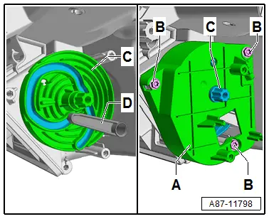
- Remove the bolts -B-.
- Remove the bracket -A-.

Installing
Install in reverse order of removal. Note the following:
- Check that the installation position and function of the connecting element and lever -C- are correct.
- Install the bracket -A-.
- Tighten the bolts -B-.
- Install the Rear Temperature Control Door Motor -V137-. Refer to → Chapter "Rear Temperature Control Door Motor -V137-, Removing and Installing".
- Perform the basic setting and the output diagnostic test mode of the A/C system. Refer to Vehicle Diagnostic Tester in the "Guided Fault Finding" function.
 Note
Note
- In this vehicle, the actuators are equipped with electronics. During the basic setting, a new control motor learns its position on the heater and A/C unit and can then be activated by the Front A/C Display Control Head -E87- (currently all actuators are identical). Refer to Vehicle Diagnostic Tester in the "Guided Fault Finding" function.
- During the basic setting, the actuators are assigned and adapted corresponding to the switching sequence of the wiring. If this sequence does not conform with the specification, the actuators will adapt incorrectly and the door control will be wrong. Refer to → Chapter "Main Wiring Diagram for A/C System Actuators".
- Check the DTC memory on the Front A/C Display Control Head -E87- and erase any displayed malfunctions. Refer to Vehicle Diagnostic Tester in the "Guided Fault Finding" function.
Bracket for Left Adjustment Motors, Removing and Installing (on a "Low"Mid" A/C System)
 Caution
The bracket holds the curved washer and a gear connection in their position.
- The bracket can only be installed with the instrument panel removed due to the connection with the control elements behind.
- Only remove the bracket when it is necessary due to an instruction.
 Note
Note
- Depending on vehicle equipment, there are different versions of the A/C system for the Audi Q7. Make sure to use the correct version and pay attention to the allocation of different components. Refer to → Chapter "A/C System Versions" and Parts Catalog.
- For this bracket to be able to be removed, the adjustment motors Defroster Door Motor -V107-, Left Side Vent Motor -V299-, and Left Temperature Control Door Motor -V158- must be removed.
- Move the driver seat as far back as possible.
- Set air distribution via the FRONT (defrost button) for the Front A/C Display Control Head -E87- to the windshield and wait until the air from the instrument panel vents flows toward the windshield.
- Turn off the ignition.
- Remove the instrument panel. Refer to → Body Interior; Rep. Gr.70; Instrument Panel; Instrument Panel, Removing and Installing.
 Note
Note
Do not remove the instrument panel crossmember, to remove the instrument panel crossmember depending on the vehicle version the windshield must be removed. Refer to → Body Interior; Rep. Gr.70; Instrument Panel; Instrument Panel, Removing and Installing.
- Remove the left footwell vent (driver side). Refer to → Chapter "Driver Side Footwell Vent, Removing and Installing".
 Caution
A/C system malfunctions in the case of interchanged control motors and/or connectors. Refer to → Chapter "Main Wiring Diagram for A/C System Actuators".
- The adjustment motors and connectors are identical. If they are installed or connected incorrectly, the corresponding doors cannot be properly adapted and/or activated.
- Clearly label the actuators and connectors prior to removal to prevent incorrect installation.
- Remove the following adjustment motors.
- Remove the Left Side Vent Motor -V299-. Refer to → Chapter "Left Side Vent Motor -V299-, Removing and Installing".
- Remove the Left Temperature Door Motor -V158-. Refer to → Chapter "Left Temperature Control Door Motor -V158-, Removing and Installing".
- Remove the Defroster Door Motor -V107-. Refer to → Chapter "Defroster Door Motor -V107-, Removing and Installing".
Removing
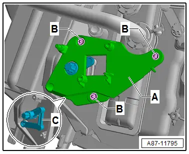
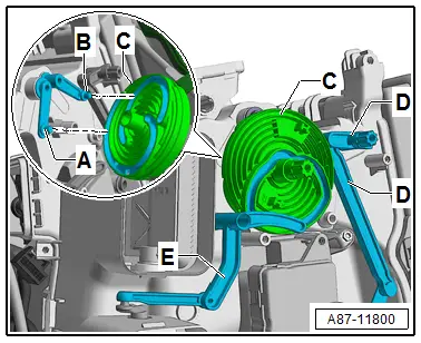
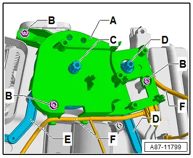
- Remove the bolts -B-.
- Detach wiring harness -F- from the bracket -A-.
- Hold the curved washer -D- and remove the bracket -A- (with the gear -C-).
Installing
Install in reverse order of removal. Note the following:
- Check the relay lever to the different doors -B and C- for the correct position in the curved washer -A- as well as the function.
- Insert the curved washer -A- and check the function.
- Check the relay lever -D- for the correct position in the curved washer -A- as well as the function.
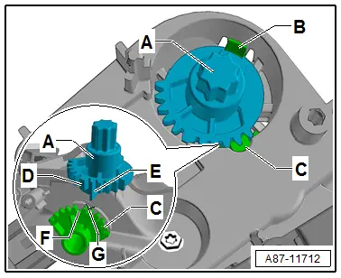
- Remove the gear -E- from the bracket -G-.
- Install the bracket -D- without the gear -E-.
- Insert the gear -E- at the same time pay attention to the correct position to the gear -F- (insert the long and wide teeth on the gear -E- correctly in the gear -F-).
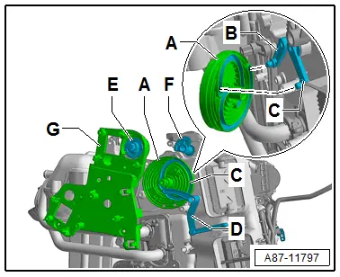
 Note
Note
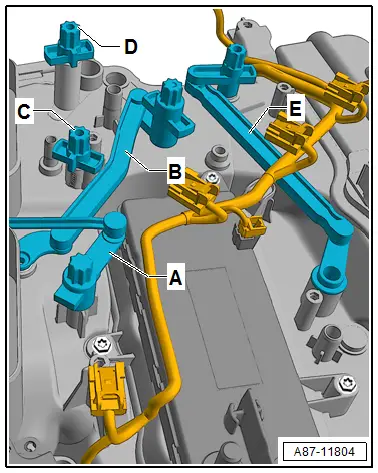
The defroster door is not operated directly by the motor but rather by the Defroster Door Motor -V107- gears. The gears -A and C- are designed with a wide tooth -D- and a long tooth -E- or with a wide tooth interval -F- and a long tooth interval -G- so that it may only be joined in one position.

- Tighten the bolts -B-.
- Insert wiring harness -F- in bracket -A- so that it cannot come into contact with moving parts.
- Check the function of the control elements -C, D and E-.
- Reinstall the removed adjustment motors in the reverse order.
- Install the wiring connections to the various adjustment motors so that they cannot come in contact with any moving parts.
- Perform the basic setting and the output diagnostic test mode of the A/C system. Refer to Vehicle Diagnostic Tester in the "Guided Fault Finding" function.
 Note
Note
- In this vehicle, the actuators are equipped with electronics. During the basic setting, a new control motor learns its position on the heater and A/C unit and can then be activated by the Front A/C Display Control Head -E87- (currently all actuators are identical). Refer to Vehicle Diagnostic Tester in the "Guided Fault Finding" function.
- During the basic setting, the actuators are assigned and adapted corresponding to the switching sequence of the wiring. If this sequence does not conform with the specification, the actuators will adapt incorrectly and the door control will be wrong. Refer to → Chapter "Main Wiring Diagram for A/C System Actuators".
- Check the DTC memory on the Front A/C Display Control Head -E87- and erase any displayed malfunctions. Refer to Vehicle Diagnostic Tester in the "Guided Fault Finding" function.

Bracket for Left Adjustment Motors, Removing and Installing (on a "Mix" or "High" A/C System)
 Caution
The gear connection is held in position via a bracket.
- The bracket can only be installed with the instrument panel removed due to the connection with the control elements behind.
- Only remove the bracket when it is necessary due to an instruction.
 Note
Note
- Depending on vehicle equipment, there are different versions of the A/C system for the Audi Q7. Make sure to use the correct version and pay attention to the allocation of different components. Refer to → Chapter "A/C System Versions" and Parts Catalog.
- So that this bracket can be removed, the Adjustment Motors -V299-, -V108-, -V110-, -V411-, -V158- and -V107- must be removed.
Removing
- Move the driver seat as far back as possible.
- Set air distribution via the FRONT (defrost button) for the Front A/C Display Control Head -E87- to the windshield and wait until the air from the instrument panel vents flows toward the windshield.
- Turn off the ignition.
- Remove the instrument panel. Refer to → Body Interior; Rep. Gr.70; Instrument Panel; Instrument Panel, Removing and Installing.
 Note
Note
Do not remove the instrument panel crossmember, to remove the instrument panel crossmember depending on the vehicle version the windshield must be removed. Refer to → Body Interior; Rep. Gr.70; Instrument Panel; Instrument Panel, Removing and Installing.
- Remove the left footwell vent (driver side). Refer to → Chapter "Driver Side Footwell Vent, Removing and Installing".
 Caution
A/C system malfunctions in the case of interchanged control motors and/or connectors. Refer to → Chapter "Main Wiring Diagram for A/C System Actuators".
- The adjustment motors and connectors are identical. If they are installed or connected incorrectly, the corresponding doors cannot be properly adapted and/or activated.
- Clearly label the actuators and connectors prior to removal to prevent incorrect installation.
- Remove the following adjustment motors.
- Remove the Left Side Vent Motor -V299-. Refer to → Chapter "Left Side Vent Motor -V299-, Removing and Installing".
- Remove the Left Footwell Door Motor -V108-. Refer to → Chapter "Left Footwell Door Motor -V108-, Removing and Installing".
- Remove the Left Footwell Temperature Control Door Motor -V411-. Refer to → Chapter "Left Footwell Temperature Control Door Motor -V411-, Removing and Installing".
- Remove the Left Center Vent Motor -V110-. Refer to → Chapter "Left Center Vent Motor -V110-, Removing and Installing".
- Remove the Left Temperature Door Motor -V158-. Refer to → Chapter "Left Temperature Control Door Motor -V158-, Removing and Installing".
- Remove the Defroster Door Motor -V107-. Refer to → Chapter "Defroster Door Motor -V107-, Removing and Installing".
Removing
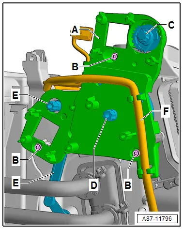
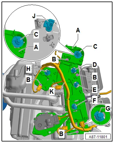
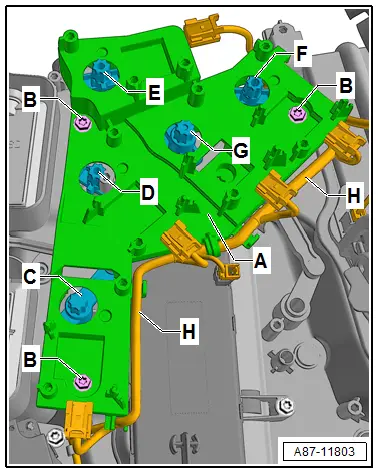
- Remove the bolts -B-.
- Detach wiring harness -K- from the bracket -A-.
- Remove the bracket -A- (with the gear -C-).

Installing
Install in reverse order of removal. Note the following:
- Check the gear -A- and the relay lever and shaft to the different doors -B to F- for the correct position and function.
- Remove the gear -C- from the bracket -A-.
- Install the bracket -A- without the gear -C-.
- Insert the gear -C- at the same time pay attention to the correct position to the gear -J- (insert the long and wide teeth on the gear -C- correctly in the gear -J-).

 Note
Note
The defroster door is not operated directly by the motor but rather by the Defroster Door Motor -V107- gears. The gears -A and C- are designed with a wide tooth -D- and a long tooth -E- or with a wide tooth interval -F- and a long tooth interval -G- so that it may only be joined in one position.
- Tighten the bolts -B-.
- Check the function of the control elements -C through H-.
- Insert wiring harness -K- in bracket -A- so that it cannot come into contact with moving parts.
- Reinstall the removed adjustment motors in the reverse order.
- Install the wiring connections to the various adjustment motors so that they cannot come in contact with any moving parts.
- Perform the basic setting and the output diagnostic test mode of the A/C system. Refer to Vehicle Diagnostic Tester in the "Guided Fault Finding" function.
 Note
Note
- In this vehicle, the actuators are equipped with electronics. During the basic setting, a new control motor learns its position on the heater and A/C unit and can then be activated by the Front A/C Display Control Head -E87- (currently all actuators are identical). Refer to Vehicle Diagnostic Tester in the "Guided Fault Finding" function.
- During the basic setting, the actuators are assigned and adapted corresponding to the switching sequence of the wiring. If this sequence does not conform with the specification, the actuators will adapt incorrectly and the door control will be wrong. Refer to → Chapter "Main Wiring Diagram for A/C System Actuators".
- Check the DTC memory on the Front A/C Display Control Head -E87- and erase any displayed malfunctions. Refer to Vehicle Diagnostic Tester in the "Guided Fault Finding" function.
- Remove the bracket -A-.
Bracket for Right Adjustment Motors, Removing and Installing (on a "Low" or "Mid" A/C System)
 Caution
The bracket holds the curved washer and a gear connection in their position.
- The bracket can only be installed with the instrument panel removed due to the connection with the control elements behind.
- Only remove the bracket when it is necessary due to an instruction.
 Note
Note
- Depending on vehicle equipment, there are different versions of the A/C system for the Audi Q7. Make sure to use the correct version and pay attention to the allocation of different components. Refer to → Chapter "A/C System Versions" and Parts Catalog.
- So that this bracket can be removed, the adjustment motors Right Side Vent Motor -V300- and Right Temperature Control Door Motor -V159-.
- Adjust the airflow direction of the air on the Front A/C Display Control Head -E87- to "DEF" (to the windshield).
- Adjust the temperature preset on the Front A/C Display Control Head -E87- for the right side to "warm" (only on a "Low" or "Mid" A/C system).
- Move the right front seat (front passenger seat) as far back as possible.
- Turn off the ignition.
- Remove the glove compartment. Refer to → Body Interior; Rep. Gr.68; Storage Compartments and Covers; Glove Compartment, Removing and Installing.
- Remove the right footwell vent (front passenger side). Refer to → Chapter "Front Passenger Side Footwell Vent, Removing and Installing".
- If equipped, remove the air duct for the glove compartment cooling. Refer to → Chapter "Air Guide for Glove Compartment Cooling, Removing and Installing".
- Remove the air duct to the instrument panel vent. Refer to → Chapter "Overview - Air Routing and Air Distribution in Passenger Compartment, Front".
 Note
Note
Do not remove the instrument panel crossmember, to remove the instrument panel crossmember depending on the vehicle version the windshield must be removed. Refer to → Body Interior; Rep. Gr.70; Instrument Panel; Instrument Panel, Removing and Installing.
 Caution
A/C system malfunctions in the case of interchanged control motors and/or connectors. Refer to → Chapter "Main Wiring Diagram for A/C System Actuators".
- The adjustment motors and connectors are identical. If they are installed or connected incorrectly, the corresponding doors cannot be properly adapted and/or activated.
- Clearly label the actuators and connectors prior to removal to prevent incorrect installation.
- Remove the following adjustment motors.
- Removing the Right Side Vent Motor -V300-. Refer to → Chapter "Right Side Vent Motor -V300-, Removing and Installing".
- Removing the Right Temperature Door Motor -V159-. Refer to → Chapter "Right Temperature Control Door Motor -V159-, Removing and Installing".
Removing
- Remove the bolts -B-.
- Detach wiring harness -F- from the bracket -A-.
- Hold the curved washer -C- and remove the bracket -A-.

Installing
Install in reverse order of removal. Note the following:
- Check the relay lever to the different doors -A and B- for the correct position in the curved washer -C- as well as the function.
- Insert the curved washer -C- and check the function.
- Check the relay lever -E- for the correct position in the curved washer -C- as well as the function.
- Check the relay lever -D- for the correct position and function.
- Install the bracket -A-.
- Tighten the bolts -B-.
- Insert wiring harness -F- in bracket -A- so that it cannot come into contact with moving parts.
- Check the function of the control elements -C, D and E-.
- Reinstall the removed adjustment motors in the reverse order.
- Install the wiring connections to the various adjustment motors so that they cannot come in contact with any moving parts.
- Perform the basic setting and the output diagnostic test mode of the A/C system. Refer to Vehicle Diagnostic Tester in the "Guided Fault Finding" function.
 Note
Note
- In this vehicle, the actuators are equipped with electronics. During the basic setting, a new control motor learns its position on the heater and A/C unit and can then be activated by the Front A/C Display Control Head -E87- (currently all actuators are identical). Refer to Vehicle Diagnostic Tester in the "Guided Fault Finding" function.
- During the basic setting, the actuators are assigned and adapted corresponding to the switching sequence of the wiring. If this sequence does not conform with the specification, the actuators will adapt incorrectly and the door control will be wrong. Refer to → Chapter "Main Wiring Diagram for A/C System Actuators".
- Check the DTC memory on the Front A/C Display Control Head -E87- and erase any displayed malfunctions. Refer to Vehicle Diagnostic Tester in the "Guided Fault Finding" function.
Bracket for Right Adjustment Motors, Removing and Installing (on a "Mix" or "High" A/C System)
 Note
Note
Depending on vehicle equipment, there are different versions of the A/C system for the Audi Q7. Make sure to use the correct version and pay attention to the allocation of different components. Refer to → Chapter "A/C System Versions" and Parts Catalog.
- Move the right front seat (front passenger seat) as far back as possible.
- Turn off the ignition.
- Remove the glove compartment. Refer to → Body Interior; Rep. Gr.68; Storage Compartments and Covers; Glove Compartment, Removing and Installing.
- Remove the right footwell vent (front passenger side). Refer to → Chapter "Front Passenger Side Footwell Vent, Removing and Installing".
- If equipped, remove the air duct for the glove compartment cooling. Refer to → Chapter "Air Guide for Glove Compartment Cooling, Removing and Installing".
- Remove the air duct to the instrument panel vent. Refer to → Chapter "Overview - Air Routing and Air Distribution in Passenger Compartment, Front".
 Note
Note
- Do not remove the instrument panel crossmember, to remove the instrument panel crossmember depending on the vehicle version the windshield must be removed. Refer to → Body Interior; Rep. Gr.70; Instrument Panel; Instrument Panel, Removing and Installing.
- So that this bracket can be removed, the adjustment motors -V109-, -V300-, -V111-, -V412-, and -V159- must be removed.
 Caution
A/C system malfunctions in the case of interchanged control motors and/or connectors. Refer to → Chapter "Main Wiring Diagram for A/C System Actuators".
- The adjustment motors and connectors are identical. If they are installed or connected incorrectly, the corresponding doors cannot be properly adapted and/or activated.
- Clearly label the actuators and connectors prior to removal to prevent incorrect installation.
- Remove the following adjustment motors.
- Remove the Right Footwell Door Motor -V109-. Refer to → Chapter "Right Footwell Door Motor -V109-, Removing and Installing".
- Removing the Right Side Vent Motor -V300-. Refer to → Chapter "Right Side Vent Motor -V300-, Removing and Installing".
- Remove the Center Vent Adjustment Motor -V111-. Refer to → Chapter "Right Center Vent Motor -V111-, Removing and Installing".
- Remove the Right Footwell Temperature Control Door Motor -V412-. Refer to → Chapter "Right Footwell Temperature Control Door Motor -V412-, Removing and Installing".
- Removing the Right Temperature Door Motor -V159-. Refer to → Chapter "Right Temperature Control Door Motor -V159-, Removing and Installing".
- Removing the Defroster Door Motor -V107-. Refer to → Chapter "Defroster Door Motor -V107-, Removing and Installing" (only on RHD vehicles).
Removing
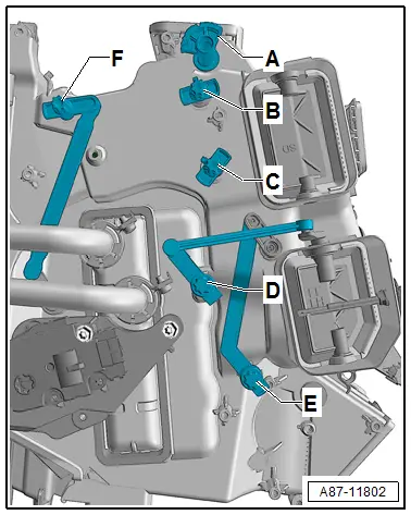
- Remove the bolts -B-.
- Detach wiring harness -H- from the bracket -A-.
- Remove the bracket -A-.
Installing
Install in reverse order of removal. Note the following:
- Check the relay lever and retaining piece to the different doors -A through E- for the correct position and function.
- Install the bracket -A-.
- Tighten the bolts -B-.
- Insert wiring harness -H- in bracket -A- so that it cannot come into contact with moving parts.
- Check the function of the control elements -C, D, E, F and G-.
- Reinstall the removed adjustment motors in the reverse order.
- Install the wiring connections to the various adjustment motors so that they cannot come in contact with any moving parts.
- Perform the basic setting and the output diagnostic test mode of the A/C system. Refer to Vehicle Diagnostic Tester in the "Guided Fault Finding" function.
 Note
Note
- In this vehicle, the actuators are equipped with electronics. During the basic setting, a new control motor learns its position on the heater and A/C unit and can then be activated by the Front A/C Display Control Head -E87- (currently all actuators are identical). Refer to Vehicle Diagnostic Tester in the "Guided Fault Finding" function.
- During the basic setting, the actuators are assigned and adapted corresponding to the switching sequence of the wiring. If this sequence does not conform with the specification, the actuators will adapt incorrectly and the door control will be wrong. Refer to → Chapter "Main Wiring Diagram for A/C System Actuators".

Rear Air Distribution Door Motor -V427- and Rear Air Quantity Motor -V443-, Removing and Installing
 Caution
The curved washer is held in position via a bracket.
Only remove the bracket when it is necessary due to an instruction.
Removing
- Remove the Rear Air Distribution Door Motor -V427- and the Rear Air Quantity Motor -V443-. Refer to → Chapter "Rear Air Distribution Door Motor -V427- and Rear Air Quantity Motor -V443-, Removing and Installing".
 Note
Note
There is a different name for this adjustment motor depending on the version of the A/C system Rear Air Distribution Door Motor -V427- on a "Low" or "Mid" A/C system and a Rear Air Quantity Motor -V443- on a "Mix" or "High" A/C system) in the same component location,
- Remove the bolts -B-.
- On a "High" A/C system hold the curved washer -C-.
- Remove the bracket -A-.

Installing
Install in reverse order of removal. Note the following:
- Check that the installation position and function of the curved washer -C- and lever -D- are correct.
- Install the bracket -A-.
- Tighten the bolts -B-.
- Install the Rear Air Distribution Door Motor -V427- and Rear Air Quantity Motor -V443-. Refer to → Chapter "Rear Air Distribution Door Motor -V427- and Rear Air Quantity Motor -V443-, Removing and Installing".
- Perform the basic setting and the output diagnostic test mode of the A/C system. Refer to Vehicle Diagnostic Tester in the "Guided Fault Finding" function.
 Note
Note
- In this vehicle, the actuators are equipped with electronics. During the basic setting, a new control motor learns its position on the heater and A/C unit and can then be activated by the Front A/C Display Control Head -E87- (currently all actuators are identical). Refer to Vehicle Diagnostic Tester in the "Guided Fault Finding" function.
- During the basic setting, the actuators are assigned and adapted corresponding to the switching sequence of the wiring. If this sequence does not conform with the specification, the actuators will adapt incorrectly and the door control will be wrong. Refer to → Chapter "Main Wiring Diagram for A/C System Actuators".
- Check the DTC memory on the Front A/C Display Control Head -E87- and erase any displayed malfunctions. Refer to Vehicle Diagnostic Tester in the "Guided Fault Finding" function.