Audi Q7: Cylinder Head
Overview - Cylinder Head
 Note
Note
The cylinder head for cylinder bank 2 (left) is shown in the illustration.
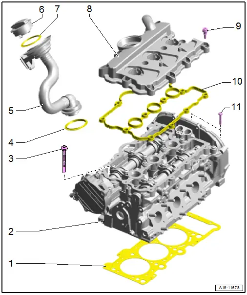
1 - Cylinder Head Gasket
- Replacing. Refer to → Chapter "Cylinder Head, Removing and Installing".
- Installation position: the part number faces the cylinder head
- Change the coolant and engine oil after replacing
2 - Cylinder Head
- Removing and installing. Refer to → Chapter "Cylinder Head, Removing and Installing".
- Checking for distortion. Refer to → Fig. "Cylinder Head, Checking for Distortion".
- Reworking Dimensions. Refer to → Fig. "Cylinder Head Reworking Dimension"
- Change the coolant and engine oil after replacing
3 - Bolt
- Replace after removing
- Follow the sequence when loosening.
- Tightening specification and sequence. Refer to → Fig. "Cylinder Head - Tightening Specification and Sequence".
4 - Seal
- Replace if damaged or leaking
5 - Oil Filler Neck
6 - Cap
7 - Seal
- Replace if damaged or leaking
8 - Cylinder Head Cover
- Removing and installing. Refer to → Chapter "Cylinder Head Cover, Removing and Installing".
9 - Bolt
- Replace if the seal is damaged
- Tightening specifications and sequence:
- Refer to → Fig. "Left Cylinder Head Cover - Tightening Specification and Sequence"
- Refer to → Fig. "Right Cylinder Head Cover - Tightening Specification and Sequence"
10 - Seal
- Replace if damaged or leaking
11 - Bolt
- Tightening specification and sequence. Refer to → Fig. "Lower Timing Chain Cover - Tightening Specification and Sequence".
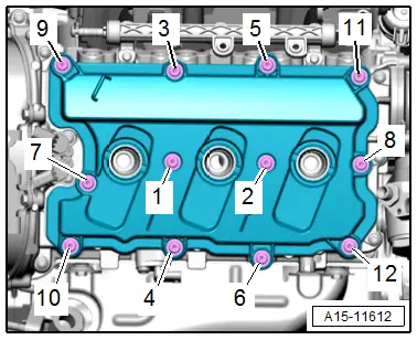
Left Cylinder Head Cover - Tightening Specification and Sequence
- Tighten the bolts to 9 Nm in the following sequence: -1 to 12-.
Right Cylinder Head Cover - Tightening Specification and Sequence
- Tighten the bolts to 9 Nm in the following sequence: -1 to 12-.
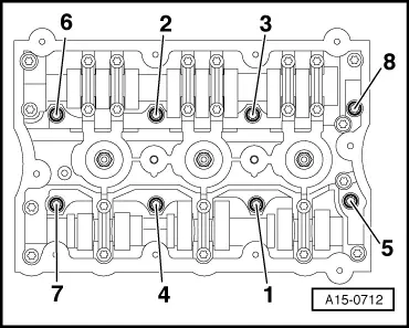
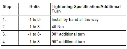
Cylinder Head - Tightening Specification and Sequence
 Note
Note
Replace the bolts that were tightened with an additional turn after removing them.
- Tighten the bolts in the steps of the sequence shown:
Cylinder Head, Checking for Distortion
- Check the cylinder head at several locations for distortion using a Straight Edge - 500mm -VAS6075- and a feeler gauge.
- Maximum distortion: 0.05 mm.
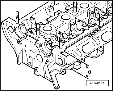
Cylinder Head Reworking Dimension
Reworking the cylinder head (face lapping) is only permissible to the minimum dimension -a-.
- Minimum dimension -a- = 139.20 mm.
Cylinder Head, Removing and Installing
Cylinder Head Bank 1 (Right), Removing and Installing
Special tools and workshop equipment required
- Commercially available XZN M12 socket, minimum 75 mm long
- Engine Bung Set -VAS6122-
Procedure
- The engine is installed.
 Note
Note
During installation, all cable ties must be installed at the same location.
- Remove the front right coolant pipe. Refer to → Chapter "Right Front Coolant Pipe, Removing and Installing".
- Remove the high pressure pipe. Refer to → Chapter "High Pressure Pipe, Removing and Installing".
- Remove the upper coolant pipe. Refer to → Chapter "Upper Coolant Pipe, Removing and Installing".
 WARNING
The fuel system is under pressure.
Risk of injury from fuel spraying out.
- Wear protective eyewear.
- Wear safety gloves.
- Reduce the pressure: place clean cloths around the connection point and carefully open the connection point.
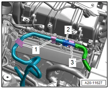
- Disconnect the fuel hose -2-. Refer to → Fuel Supply - Gasoline Engines; Rep. Gr.20; Connector Couplings; Connector Couplings, Disconnecting.
- Always seal the open lines and connections with clean plugs from the Engine Bung Set -VAS6122-.
- Free up the fuel hose from the clips -1 and 3- and move it to the right side.
- Remove the right camshafts. Refer to → Chapter "Camshaft, Removing and Installing".
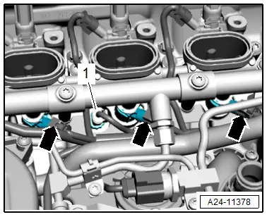
- Disconnect the connectors -arrows- on the fuel injectors.
- Disconnect the connector -1- on the Engine Temperature Control Sensor -G694-.
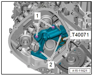
- Remove the bolts -1 and 2- and the chain tensioner from the cylinder head.
 Note
Note
The Locking Pin -T40071- remains inserted.
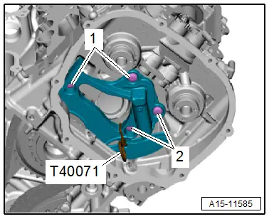
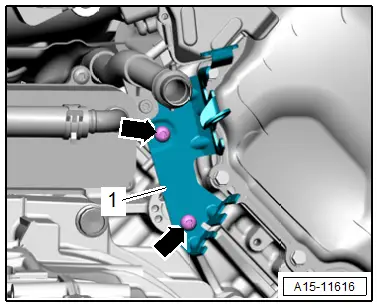
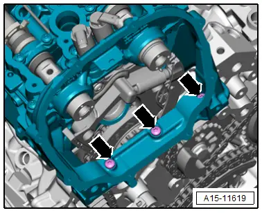
- Remove the bolts -arrows- and the bracket -1-.
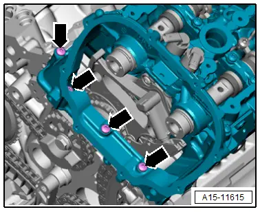
- Remove the bolts -arrows- on the rear of the cylinder head.
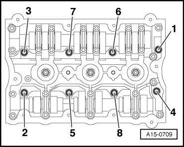
- Loosen the cylinder head bolts in the sequence -1 to 8-.
- Remove the bolts, remove the cylinder head and place it on a soft surface (foam).
Cylinder Head Bank 2 (Left), Removing
Special tools and workshop equipment required
- Commercially available XZN M12 socket, minimum 75 mm long
Procedure
- The engine is installed.
 Note
Note
During installation, all cable ties must be installed at the same location.
- Remove the MPI injection fuel line. Refer to → Chapter "Fuel Line, Removing and Installing".
- Remove the left camshafts. Refer to → Chapter "Camshaft, Removing and Installing".
- Remove the front left coolant pipe. Refer to → Chapter "Front Left Coolant Pipe, Removing and Installing".
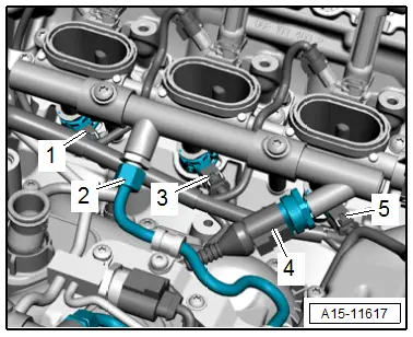
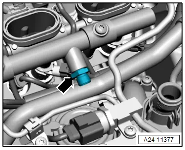
- Disconnect electrical connectors -1 and 3- on fuel injectors.
- Disconnect the connector -4- from the Fuel Pressure Sensor -G247-.
 WARNING
The fuel system is under pressure.
Risk of injury from fuel spraying out.
- Wear protective eyewear.
- Wear safety gloves.
- Reduce the pressure: place clean cloths around the connection point and carefully open the connection point.
- Remove the union nut -2-.
 Note
Note
The connector -5- is disconnected later.
- If the connection -arrow- is loosened of removed, it must be replaced.
- Remove the bolts -1 and 2- and the chain tensioner from the cylinder head.
 Note
Note
The Locking Pin -T40071- remains inserted.
- Free up the wires.
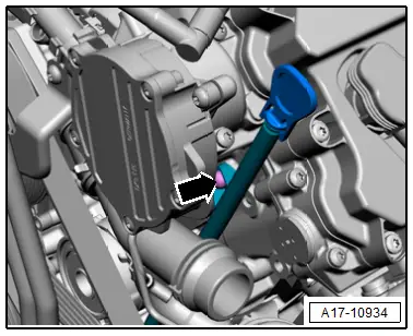
- Remove the bolt -arrow- and the oil dipstick tube.
- Remove the bolts -arrows- on the rear of the cylinder head.
- Loosen the cylinder head bolts in the sequence -1 to 8-.
- Remove the bolts the cylinder head and the cylinder "4" fuel injector connector.
- Place the cylinder head on a soft surface (foam).

Cylinder Head, Installing
Special tools and workshop equipment required
- Camshaft Clamps -T40133-
- Crankshaft Locking Pin -T40069-
 Caution
This procedure contains mandatory replaceable parts. Refer to component overview prior to starting procedure.
Mandatory Replacement Parts
- Bolts - Cylinder head
- Gaskets - Cylinder head
- Seals - Oil filler neck
- Seals - Coolant pipe
- Gasket - Cylinder head cover
Procedure
 Caution
There is a risk of damaging the sealing surfaces.
- Carefully remove the sealant residue from the cylinder head and cylinder block.
- Make sure that no long scrapes or scratches result.
Risk of damaging the cylinder block.
No oil or coolant must be in the cylinder head bolt blind holes in the cylinder block.
Risk of leaks in cylinder head gasket.
- Carefully remove the sealant residue from cylinder head and cylinder block. Make sure that no long scrapes or scratches result.
- Carefully remove all lapping and sanding residue.
- Only unpack the new cylinder head gasket immediately before installing.
- To prevent the cylinder head gasket silicone layer and recessed area from being damaged, always handle the gasket extremely carefully.
There is a risk of damaging open valves.
If a replacement cylinder is installed, only remove the plastic base right before cylinder head is installed to protect open valves.
Risk of damaging the valves and piston crowns after working on valvetrain.
To ensure valves do not strike pistons when starting, carefully rotate the engine at least two full revolutions.
 Note
Note
- Replace the bolts that were tightened with an additional turn after removing them.
- Replace self-locking nuts, gaskets, seals and O-rings after removing.
- Note different sealant for cylinder head sealing surfaces and bolts. Refer to the Parts Catalog.
- If a replacement cylinder is installed, the contact surfaces between the hydraulic lifters, roller rocker levers and cam running surfaces must be lubricated before installing the cylinder head cover.
- The coolant and engine oil must be changed whenever replacing the cylinder head or cylinder head seal.
- If the connection -arrow- is loosened of removed, it must be replaced.

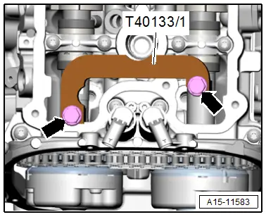
- Camshafts on the right cylinder head secured in "TDC" using the Camshaft Clamp -T40133/1--arrows- (25 Nm).
- The Camshaft Clamp -T40133/1- is correctly positioned when the holes for the cylinder head bolts remain free.
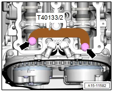
- Camshafts on the left cylinder head secured in "TDC" using the Camshaft Clamp -T40133/2--arrows- (25 Nm).
- The Camshaft Clamp -T40133/2- is correctly positioned when the holes for the cylinder head bolts remain free.
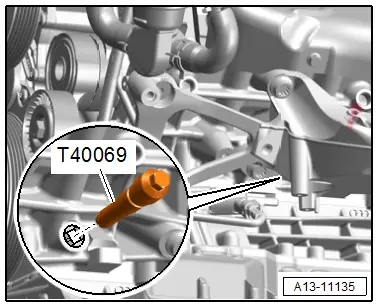
- Secure crankshaft in "TDC" position using Crankshaft Locking Pin -T40069-.
- Install the new seals on the coolant pipe.
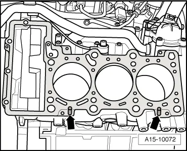
- Position the cylinder head gasket.
- Installed position: the marking "oben" (top) or the part number must be legible.
- Pay close attention to alignment bushings in cylinder block -arrows-.
- Position the cylinder head.
- Tighten the cylinder head bolts. Refer to → Fig. "Cylinder Head - Tightening Specification and Sequence".
- Tighten the bolts -arrows-.
 Note
Note
It is not required to retighten the cylinder head bolts after repairs.
Installation is performed in reverse order of removal, while noting the following:
- Install the bracket for the wire. Refer to → Chapter "Overview - Timing Chain Cover".
- Install the chain tensioner. Refer to → Chapter "Overview - Camshaft Timing Chains".
- Install the camshafts. Refer to → Chapter "Camshaft, Removing and Installing".
- Install the left front coolant pipe. Refer to → Chapter "Front Left Coolant Pipe, Removing and Installing".
- Install the MPI injection fuel line. Refer to → Chapter "Fuel Line, Removing and Installing".
- Connect the fuel hose. Refer to → Fuel Supply System; Rep. Gr.20; Connector Couplings; Connector Couplings, Disconnecting.
- Install the upper coolant pipe. Refer to → Chapter "Upper Coolant Pipe, Removing and Installing".
- Install the high pressure pipe. Refer to → Chapter "High Pressure Pipe, Removing and Installing".
- Install the right front coolant pipe. Refer to → Chapter "Right Front Coolant Pipe, Removing and Installing".
- Connections and wire routing. Refer to → Wiring diagrams, Troubleshooting & Component locations.
- Change the engine oil.
- Change the coolant. Refer to → Chapter "Coolant, Draining and Filling".

Tightening Specifications
- Refer to → Fig. "Cylinder Head - Tightening Specification and Sequence"
- Refer to → Fig. "Oil Dipstick Tube - Tightening Specification"
- Refer to → Chapter "Overview - Fuel Rail with Fuel Injectors"
Cylinder Head Cover, Removing and Installing
Removing
 Caution
This procedure contains mandatory replaceable parts. Refer to component overview prior to starting procedure.
Mandatory Replacement Parts
- Bolts - Cylinder head cover(s)
- Seal(s) - Cylinder head cover
- Remove the ignition coils. Refer to → Chapter "Ignition Coils with Power Output Stages, Removing and Installing".
- Remove the engine cover. Refer to → Chapter "Engine Cover, Removing and Installing".
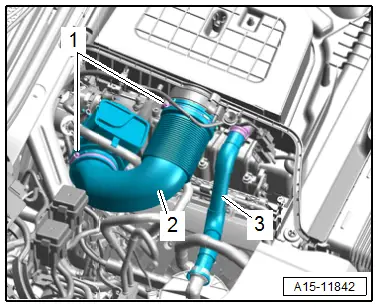
Cylinder Bank 1 (Right):
- Loosen the hose clamps -1- and remove the air duct pipe -2-.
- Remove the secondary air injection pipe -3- to do so push the release buttons on both sides.
- Free up the fuel hose -2- from the clips -1 and 3-.

- Remove the bolts in the sequence -12 to 1- and remove the cylinder head cover.

Cylinder Bank 2 (Left):
 Note
Note
It is not possible to remove the crankcase ventilation hose -arrow- from the cylinder head cover without damaging it.
- Remove the bolts in the following sequence: -12 to 1-.
- Move the cylinder head cover with the crankcase ventilation hose connected -arrow- to the side.
If the Cylinder Head Cover Is to Be Removed:
- Remove the hose for the crankcase ventilation. Refer to → Chapter "Crankcase Ventilation Hose, Removing and Installing".
Installing
Install in reverse order of removal and note the following:
 Note
Note
- Replace the O-ring after removing.
- Replace a damaged cylinder head cover seal.
- Replace the cylinder head cover bolts after removing the damaged seal.
- Secure all hose connections with hose clamps that match the ones used in series production. Refer to the Parts Catalog.
- Clean any oil or grease off the sealing surfaces.
- Install the engine cover. Refer to → Chapter "Engine Cover, Removing and Installing".
- Install the ignition coils. Refer to → Chapter "Ignition Coils with Power Output Stages, Removing and Installing".
Tightening Specifications
- Refer to → Fig. "Left Cylinder Head Cover - Tightening Specification and Sequence"
- Refer to → Fig. "Right Cylinder Head Cover - Tightening Specification and Sequence"
- Refer to → Chapter "Overview - Charge Air Hose Connections"
- Refer to → Chapter "Overview - Crankcase Ventilation"
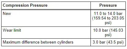
Compression, Checking
Special tools and workshop equipment required
- Spark Plug Removal Tool -3122B-
- Compression Tester Kit -VAG1763-
Procedure
- Engine oil temperature at least 30 ℃ (86 ºF).
- Battery voltage at least 12.5 V.
- Remove the ignition coils. Refer to → Chapter "Ignition Coils with Power Output Stages, Removing and Installing".
- Remove the air filter housing. Refer to → Chapter "Air Filter Housing, Removing and Installing".
- Remove the Throttle Valve Control Module -J338-. Refer to → Chapter "Throttle Valve Control Module -J338-, Removing and Installing".
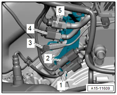
- Disconnect the connectors -4 and 5- to the fuel injectors on the rear of the left cylinder head.
 Note
Note
Ignore -1, 2 and 3-.
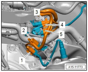
- Disconnect the connectors -2 and 3- to the fuel injectors on the rear of the right cylinder head.
 Note
Note
Ignore items -1, 4 and 5-.
- Remove the spark plugs with Spark Plug Removal Tool -3122B-.
- Install the Throttle Valve Control Module -J338- and connect the connector for the test.
- Check the compression using the Compression Tester Kit -VAG1763-.
 Note
Note
Information on using the tester. Refer to the Operating Instructions.
- Have a second mechanic press the accelerator pedal down all the way while operating the starter until the pressure increase is no longer displayed on the tester.
- Repeat the procedure on each cylinder.
Assemble in the reverse order of removal. Note the following:
- Install the spark plugs.
- Install the Throttle Valve Control Module -J338-. Refer to → Chapter "Throttle Valve Control Module -J338-, Removing and Installing".
- Install the air filter housing. Refer to → Chapter "Air Filter Housing, Removing and Installing".
- Install the ignition coils. Refer to → Chapter "Ignition Coils with Power Output Stages, Removing and Installing".
- Connections and wire routing. Refer to → Wiring diagrams, Troubleshooting & Component locations.
Erase DTC entries which have occurred during the testing:
- Connect the Vehicle Diagnostic Tester.
- Switch the ignition on.
- Select and start the Diagnostic operating mode.
- Select the Test plan tab.
- Select the button Individual tests and select the following tree structures one after the other:
- Drivetrain
- TFSI V6
- 01 - OBD-capable systems
- Simos Fuel Injection and Ignition
- Functions
- Readiness code

