Audi Q7: Component Location Overview - Components Outside of Vehicle Interior
Component Location Overview - Components Outside of Passenger Compartment, Front Component Group "1"
Components on the vehicle front and in the engine compartment
 Note
Note
Depending on vehicle equipment, there are different versions of the A/C system for the Audi Q7. Make sure to use the correct version and pay attention to the allocation of different components. Refer to → Chapter "A/C System Versions" and Parts Catalog.
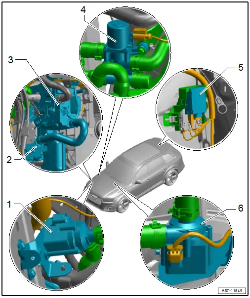
1 - Coolant Recirculation Pump -V50-
- With TDI-engine
- Refer to → Chapter "A/C System Temperature Door Heat Output Activation, Checking"
- Refer to → Chapter "Coolant Recirculation Pump -V50-, Function"
- Refer to → Chapter "Incorporating the Heating and A/C System in the Coolant Circuit"
 Note
Note
The activation of the Coolant Recirculation Pump -V50- varies. In most vehicles, it is activated by the Engine Control Module -J623- at the request of the Front A/C Display Control Head -E87-. Refer to Vehicle Diagnostic Tester in the "Guided Fault Finding" function and the → Wiring diagrams, Troubleshooting & Component locations.
2 - Recirculation Pump -V55-
- Only with parking heater
- The Recirculation Pump -V55- is activated by the Auxiliary Heater Control Module -J364-
- Depending on the vehicle equipment the Auxiliary Heater Control Module -J364- from the Recirculation Pump - V55- switches on, also with the parking/auxiliary heater switched off due to a request that is received via the data bus (request for example from Engine Control Module -J623- or from the Front A/C Display Control Head -E87-.
- Removing and installing. Refer to → Heating, Ventilation and Air Conditioning; Rep. Gr.82; Parking/Auxiliary Heater; Recirculation PumpV55 Removing and Installing.
3 - Parking Heater with the Auxiliary Heater Control Module -J364-
- Equipped on some models
- On vehicles with a gasoline engine currently no Auxiliary Heater Heating Element -Z35- is installed as an auxiliary heater. The parking heater installed as optional equipment is activated as an auxiliary heater depending on the vehicle version.
4 - Heater Coolant Shut-Off Valve -N279-
- The Heater Coolant Shut-Off Valve -N279- is currently only installed in vehicles with a "parking heater". Refer to → Rep. Gr.19; Coolant System/Coolant; Connection Diagram - Coolant Hoses. In vehicles with a parking heater, it assumes the function of the Coolant Shut-Off Valve -N82-.
- Refer to → Chapter "Heater Coolant Shut-Off Valve -N279- Function"
- Refer to → Chapter "Incorporating the Heating and A/C System in the Coolant Circuit"
5 - Parking Heater Radio Receiver -R64-
- Equipped on some models
- As soon as an activation signal is detected by the hand-held transmitter of the parking heater radio receiver/remote control, the Auxiliary Heater Control Module -J364- queries the Front A/C Display Control Head -E87-. The Front A/C Display Control Head -E87- then decides whether parking heater operation is necessary to reach the set temperatures or parking ventilation operation is sufficient.
6 - Coolant Recirculation Pump -V50-
- With gasoline engine
- Refer to → Chapter "A/C System Temperature Door Heat Output Activation, Checking"
- Refer to → Chapter "Coolant Recirculation Pump -V50-, Function"
- Refer to → Chapter "Incorporating the Heating and A/C System in the Coolant Circuit"
 Note
Note
The activation of the Coolant Recirculation Pump -V50- varies. In most vehicles, it is activated by the Engine Control Module -J623- at the request of the Front A/C Display Control Head -E87-. Refer to Vehicle Diagnostic Tester in the "Guided Fault Finding" function and the → Wiring diagrams, Troubleshooting & Component locations.
Component Location Overview - Components Outside of Passenger Compartment, Front Component Group "2"
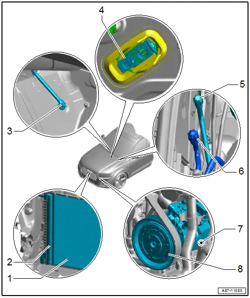
1 - Condenser
- Overview. Refer to → Chapter "Overview - Refrigerant Circuit Components".
2 - Dryer Cartridge
- Overview. Refer to → Chapter "Overview - Condenser, Dryer Bag/Dryer Cartridge".
3 - Condensation Water Drain
- Checking. Refer to → Chapter "Condensation Water Drain, Checking".
- Removing and installing. Refer to → Chapter "Condensation Water Drain, Removing and Installing".
4 - Expansion Valve
- Overview. Refer to → Chapter "Overview - Refrigerant Lines in Plenum Chamber and Front Expansion Valve".
5 - Low Pressure Side Service Connection
- For measuring and discharging
 Caution
Danger due to refrigerant coming out under pressure when there is a faulty valve in the refrigerant circuit.
Danger of frost bite to skin and other parts of the body.
Only remove when the refrigerant circuit is empty. The connection does not have a valve. Refer to A/C System - with Refrigerant R134a.
- Overview. Refer to → Chapter "Overview - Refrigerant Lines in Plenum Chamber and Front Expansion Valve".
6 - High Pressure Side Service Connection
- For measuring, discharging and charging
 Caution
Danger due to refrigerant coming out under pressure when there is a faulty valve in the refrigerant circuit.
Danger of frost bite to skin and other parts of the body.
Only remove when the refrigerant circuit is empty. The connection does not have a valve. Refer to A/C System - with Refrigerant R134a.
- Overview. Refer to → Chapter "Overview - Refrigerant Lines in Plenum Chamber and Front Expansion Valve".
7 - A/C Compressor Regulator Valve -N280-
- Check activation and function. Refer to → Chapter "A/C Compressor Regulator Valve -N280-, Checking Switch-On Signal".
 Note
Note
- The A/C Compressor Regulator Valve -N280- is activated by the Vehicle Electrical System Control Module -J519-. Refer to → Chapter "A/C Compressor Regulator Valve -N280-, Checking Switch-On Signal". The Front A/C Display Control Head -E87- first transmits the request to activate the A/C Compressor Regulator Valve -N280- via the data bus to the Data Bus On Board Diagnostic Interface -J533-. From there, the request is transmitted to the -J519-. Refer to Vehicle Diagnostic Tester in the "Guided Fault Finding" function and refer to → Wiring diagrams, Troubleshooting & Component locations.
- Certain malfunctions at the A/C Compressor Regulator Valve -N280- (for example, a stuck valve or a short circuit in the coil) can lead to a complaint regarding the A/C compressor (A/C system is not cooling, the evaporator ices over, etc.). If the cause is with the A/C compressor regulator valve -N280- (and not the A/C compressor itself), the A/C compressor can be serviced by replacing the valve -N280-. Refer to → Refrigerant R134a Servicing; Rep. Gr.87; Refrigerant Circuit Components, Replacing.
- The A/C Compressor Regulator Valve -N280- is not available as a replacement part for all A/C compressors. If the A/C Compressor Regulator Valve -N280- is not available as an individual A/C compressor part (different versions), then the entire A/C compressor must be replaced if there is a complaint. Refer to the Parts Catalog.
8 - A/C Compressor
- Refer to the Parts Catalog for the allocation.
- Overview. Refer to → Chapter "Overview - A/C Compressor Power Unit".
Component Location Overview - Components Outside of Passenger Compartment, Front Component Group "3"
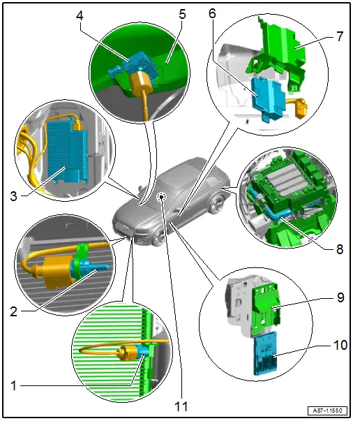
1 - High Pressure Sensor -G65-
- Refer to → Chapter "High Pressure Sensor -G65-, Checking, Removing and Installing"
- To check the signal. Refer to Vehicle Diagnostic Tester in the "Guided Fault Finding" function.
 Note
Note
The High Pressure Sensor -G65- exchanges information via a local data bus with the Front A/C Display Control Head -E87-. Refer to Vehicle Diagnostic Tester in the "Guided Fault Finding" function and refer to → Wiring diagrams, Troubleshooting & Component locations.
2 - Outside Air Temperature Sensor -G17-
- The measured value of the Outside Air Temperature Sensor -G17- is evaluated by the Vehicle Electrical System Control Module -J519- and is transmitted via the data bus to the Front A/C Display Control Head -E87-. Refer to Vehicle Diagnostic Tester in the "Guided Fault Finding" function and refer to → Wiring diagrams, Troubleshooting & Component locations.
- Refer to → Chapter "Outside Air Temperature Sensor -G17-, Removing and Installing"
3 - Windshield Defogger Control Module -J505-
- Equipped on some models
- Notes regarding the activation of the Windshield Defogger -Z2-. Refer to → Chapter "Windshield Defogger".
- Removing and installing. Refer to → Chapter "Windshield Defogger Control Module -J505-, Removing and Installing".
4 - Humidity Sensor in Fresh Air Intake Duct -G657- with or without Air Quality Sensor -G238-
- On a vehicle with a "Low" or "Mid" A/C system no Air Quality Sensor -G238- is installed
- On a vehicle with a "Mix" or "High" A/C system the Air Quality Sensor -G238- and the Humidity Sensor in Fresh Air Intake Duct -G657- are combined in a single component.
- Function mode. Refer to → Chapter "Air Quality Sensor -G238- Function".
- Checking. Refer to → Chapter "Air Quality Sensor -G238- Functionality, Checking".
- Removing and installing. Refer to → Chapter "Air Quality Sensor -G238- with the Humidity Sensor In Fresh Air Intake Duct -G657-, Removing and Installing".
- The measured value of the Air Quality Sensor -G238- and the Humidity Sensor in Fresh Air Intake Duct -G657- are evaluated by the Front A/C Display Control Head -E87-. Upon request, the Front A/C Display Control Head -E87- switches to recirculating air mode if no shut-off condition is present. Refer to Vehicle Diagnostic Tester in the "Guided Fault Finding" function.
5 - Fresh Air Intake Inner Cover
6 - Data Bus On Board Diagnostic Interface -J533-
- Via the Data Bus On Board Diagnostic Interface -J533-, information is exchanged between the Climatronic Control Module -J255- control head and other control modules (for example with the Comfort System Central Control Module -J393-, the Vehicle Electrical System Control Module -J519- etc.). Refer to Vehicle Diagnostic Tester in the "Guided Fault Finding" function and → Wiring diagrams, Troubleshooting & Component locations.
- Removing and installing. Refer to → Electrical Equipment; Rep. Gr.97; Control Modules; Data Bus on Board Diagnostic Interface J533, Removing and Installing.
7 - Bracket
- For Data Bus on Board Diagnostic Interface -J533-
8 - Comfort System Central Control Module -J393-
- The activation of various vehicle systems (for example the Rear Window Defogger -Z1- etc.), such as the evaluation of the signals for other components (for example signals from the Humidity Sensor -G355-) occurs via the comfort system central control module -J393-. Refer to Vehicle Diagnostic Tester in the "Guided Fault Finding" Function and → Wiring diagrams, Troubleshooting & Component locations.
- Removing and installing. Refer to → Body Exterior; Rep. Gr.57; Central Locking; Comfort System Central Control ModuleJ393, Removing and Installing.
9 - Bracket
- For Vehicle Electrical System Control Module -J519-
10 - Vehicle Electrical System Control Module -J519-
- Different components (for example, the A/C Compressor Regulator Valve -N280-, etc.) are activated by the A/C system via the vehicle electrical system control module -J519-. Refer to Vehicle Diagnostic Tester in the "Guided Fault Finding" function (for the A/C system and the vehicle electrical system control module -J519-).
- Removing and installing and checking. Refer to → Electrical Equipment; Rep. Gr.97; Control Modules; Data Bus on Board Diagnostic Interface J533, Removing and Installing
11 - Windshield Defogger -Z2-
- Equipped on some models
- Activation occurs via the Windshield Defogger Control Module -J505-.
- Windshield removing and Installing. Refer to → Body Exterior; Rep. Gr.64; Windshield; Windshield, Removing and Installing.
Component Location Overview - Rear Components Outside of Passenger Compartment
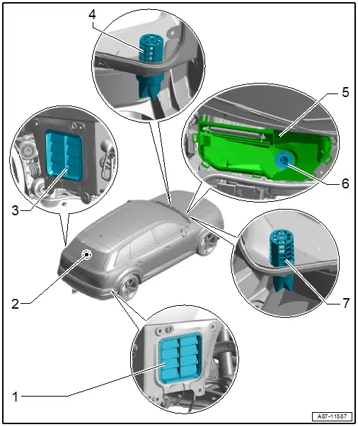
1 - Right Vehicle Interior Forced Air Extraction
- Checking. Refer to → Chapter "Vehicle Interior Forced Air Extraction, Removing and Installing".
- Removing and installing. Refer to → Chapter "Vehicle Interior Forced Air Extraction, Removing and Installing".
2 - Rear Window Defogger -Z1-
- The request to the rear window defogger is sent by the Front A/C Display Control Head -E87- via the data bus to the Comfort System Central Control Module -J393-. The Rear Window Defogger -Z1- is actuated by the Comfort System Central Control Module -J393-. Refer to → Wiring diagrams, Troubleshooting & Component locations and Vehicle Diagnostic Tester in the "Guided Fault Finding" function.
- Notes on function of the rear window defogger. Refer to → Chapter "Rear Window Defogger".
- Rear window, removing and installing. Refer to → Body Exterior; Rep. Gr.64; Rear Window; Rear Window, Removing and Installing.
3 - Left Vehicle Interior Forced Air Extraction
- Checking. Refer to → Chapter "Vehicle Interior Forced Air Extraction, Removing and Installing".
- Removing and installing. Refer to → Chapter "Vehicle Interior Forced Air Extraction, Removing and Installing".
4 - Left Plenum Chamber Water Drain
- Checking and cleaning. Refer to → Chapter "Plenum Chamber Water Drain, Removing and Installing".
5 - Fresh Air Intake
- Removing and installing. Refer to → Chapter "Fresh Air Intake, Removing and Installing".
- Make sure the intake grille fits correctly. The intake grille prevents foreign objects such as leaves from getting into the heater and A/C unit air intake shroud.
- Depending on the version, for some countries with high dust levels (for example China), a filter is installed instead of intake air grille, which prevents dust and sand from entering the fresh air blower. Refer to → Chapter "Fresh Air Intake, Removing and Installing" and Parts Catalog.
6 - Fresh Air Intake Water Drain
- Checking and cleaning. Refer to → Chapter "Plenum Chamber Water Drain, Removing and Installing".
7 - Right Plenum Chamber Water Drain
- Checking and cleaning. Refer to → Chapter "Plenum Chamber Water Drain, Removing and Installing".

