Audi Q7: Overview - Attachments for Heater and A/C Unit and Air Intake Housing
General information for "Mid"/"Mix" and "High" A/C System
 Caution
Interchange of the wire connections to the temperature sensors or the connectors at the adjustment motors results in problems regarding the regulation of the A/C system.
A/C system malfunctions in the case of interchanged control motors and/or connectors. Refer to → Chapter "Main Wiring Diagram for A/C System Actuators".
- Interchanged connectors at the adjustment motors or the temperature sensors are not identified as malfunctions by the Rear A/C Display Control Head -E265-.
- Prior to disconnecting connectors or removing electrical components, clearly label them in order to rule out confusion.
 Note
Note
- Depending on vehicle equipment, there are different versions of the A/C system for the Audi Q7. Make sure to use the correct version and pay attention to the allocation of different components. Refer to → Chapter "A/C System Versions" and Parts Catalog.
- Depending on the vehicle equipment either a rear heater and A/C unit (on a vehicle with a "High" A/C system), a rear air distribution housing (on a vehicle with a "Mid" or "Mix" A/C system) or only a rear air duct on a vehicle with a "Low" A/C system) are installed. Refer to → Chapter "Overview - Air Routing and Air Distribution in Vehicle Interior".
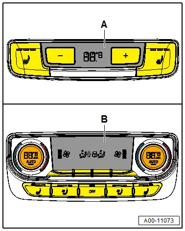
- The Rear A/C Display Control Head -E265- is an optional equipment (for "Mid", "Mix", or "High" A/C system) different versions -A or B-. Refer to the Parts Catalog.
- For the start of production only on vehicles with a "Mid", "Mix" or "High" A/C system a Rear A/C Display Control Head -E265- is installed.
Overview - Heater and A/C Unit Attachments and Air Intake Housing, Heater Core, "Mid" or "Mix" A/C System
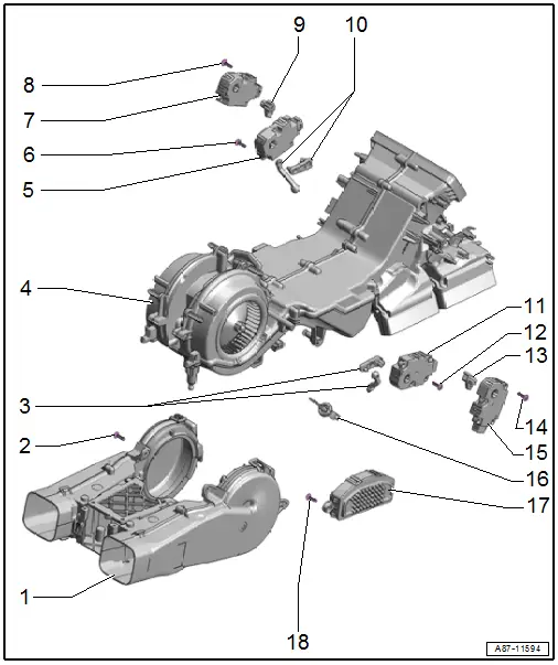
1 - Air Duct
- Removing and installing. Refer to → Chapter "Rear Fresh Air Blower -V80-, Removing and Installing, Mid or Mix A/C System".
2 - Bolt
- 1 Nm
- Quantity: 2
3 - Operating Lever
- Mark before removing (risk of interchange)
4 - Rear Heater and A/C Unit
- With Rear Fresh Air Blower -V80-
- Removing and installing. Refer to → Chapter "Heater and A/C Unit, Removing and Installing, Mid or Mix A/C System".
5 - Right B-Pillar/Footwell Shut-Off Door Motor -V211-
- To rule out confusion, clearly label the wire routing, allocation and adjustment motor for each installation location prior to disconnecting the connector or removing an adjustment motor.
- Refer to → Chapter "Right B-Pillar/Footwell Shut-Off Door Motor -V211-, Removing and Installing"
6 - Bolt
- 1 Nm
- Quantity: 2
7 - Right Rear Upper Body Vent Motor -V316-
- To rule out confusion, clearly label the wire routing, allocation and adjustment motor for each installation location prior to disconnecting the connector or removing an adjustment motor.
- Refer to → Chapter "Right Rear Upper Body Vent Motor -V316-"
8 - Bolt
- 1 Nm
- Quantity: 2
9 - Operating Lever
- Mark before removing (risk of interchange)
10 - Operating Lever
- Mark before removing (risk of interchange)
11 - Left B-Pillar/Footwell Shut-Off Door Motor -V212-
- To rule out confusion, clearly label the wire routing, allocation and adjustment motor for each installation location prior to disconnecting the connector or removing an adjustment motor.
- Refer to → Chapter "Left B-Pillar/Footwell Shut-Off Door Motor -V212-, Removing and Installing"
12 - Bolt
- 1 Nm
- Quantity: 2
13 - Operating Lever
- Mark before removing (risk of interchange)
14 - Bolt
- 1 Nm
- Quantity: 2
15 - Left Rear Upper Body Vent Motor -V315-
- To rule out confusion, clearly label the wire routing, allocation and adjustment motor for each installation location prior to disconnecting the connector or removing an adjustment motor.
- Refer to → Chapter "Left Rear Upper Body Vent Motor -V315-"
16 - Rear Upper Body Vent Temperature Sensor -G537-
- Check. Refer to Vehicle Diagnostic Tester in the "Guided Fault Finding" function
- Removing and installing. Refer to → Chapter "Rear Upper Body Vent Temperature Sensor -G537-, Removing and Installing".
17 - Rear Fresh Air Blower Control Module -J391-
- Ensure the correct allocation. Refer to the Parts Catalog.
- To check. Refer to Vehicle Diagnostic Tester in the "Guided Fault Finding" function
- Refer to → Chapter "Fresh Air Blower Control Module, Removing and Installing "
18 - Bolt
- 2 Nm
- Quantity: 2
Overview - Heater and A/C Unit Attachments and Air Intake Housing, Heater Core, "High" A/C System Section 1
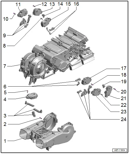
1 - Air Duct
- With recirculation doors and various levers
- Do not disassemble further
- Removing and installing. Refer to → Chapter "Rear Fresh Air Blower -V80-, Removing and Installing, High A/C System".
2 - Bolt
- 1 Nm
- Quantity: 2
3 - Operating Lever
- Mark before removing (risk of interchange)
4 - Rear Recirculation Door Motor -V421-
- To rule out confusion, clearly label the wire routing, allocation and adjustment motor for each installation location prior to disconnecting the connector or removing an adjustment motor.
- Refer to → Chapter "Rear Recirculation Door Motor -V421-, Removing and Installing"
5 - Bolt
- 1 Nm
- Quantity: 2
6 - Operating Lever
- Mark before removing (risk of interchange)
7 - Rear Heater and A/C Unit
- Refer to → Chapter "Heater and A/C Unit, Removing and Installing, High A/C System"
8 - Bolt
- 1 Nm
- Quantity: 2
9 - Operating Lever
- Mark before removing (risk of interchange)
10 - Bolt
- 1 Nm
- Quantity: 2
11 - Right Rear Temperature Control Door Motor -V314-
- To rule out confusion, clearly label the wire routing, allocation and adjustment motor for each installation location prior to disconnecting the connector or removing an adjustment motor.
- Refer to → Chapter "Right Rear Temperature Control Door Motor -V314-, Removing and Installing"
12 - Bolt
- 1 Nm
- Quantity: 2
13 - Right Rear Upper Body Vent Motor -V316-
- To rule out confusion, clearly label the wire routing, allocation and adjustment motor for each installation location prior to disconnecting the connector or removing an adjustment motor.
- Refer to → Chapter "Right Rear Upper Body Vent Motor -V316-"
14 - Operating Lever
- Mark before removing (risk of interchange)
15 - Right B-Pillar/Footwell Shut-Off Door Motor -V211-
- Refer to → Chapter "Right B-Pillar/Footwell Shut-Off Door Motor -V211-, Removing and Installing"
- To rule out confusion, clearly label the wire routing, allocation and adjustment motor for each installation location prior to disconnecting the connector or removing an adjustment motor.
16 - Operating Lever
- Mark before removing (risk of interchange)
17 - Left Rear Temperature Control Door Motor -V313-
- To rule out confusion, clearly label the wire routing, allocation and adjustment motor for each installation location prior to disconnecting the connector or removing an adjustment motor.
- Refer to → Chapter "Left Rear Temperature Control Door Motor -V313-, Removing and Installing"
18 - Bolt
- 1 Nm
- Quantity: 2
19 - Operating Lever
- Mark before removing (risk of interchange)
20 - Bolt
- 1 Nm
- Quantity: 2
21 - Left Rear Upper Body Vent Motor -V315-
- To rule out confusion, clearly label the wire routing, allocation and adjustment motor for each installation location prior to disconnecting the connector or removing an adjustment motor.
- Refer to → Chapter "Left Rear Upper Body Vent Motor -V315-"
22 - Bolt
- 1 Nm
- Quantity: 2
23 - Left B-Pillar/Footwell Shut-Off Door Motor -V212-
- To rule out confusion, clearly label the wire routing, allocation and adjustment motor for each installation location prior to disconnecting the connector or removing an adjustment motor.
- Refer to → Chapter "Left B-Pillar/Footwell Shut-Off Door Motor -V212-, Removing and Installing"
24 - Operating Lever
- Mark before removing (risk of interchange)
Overview - Heater and A/C Unit Attachments and Air Intake Housing, Heater Core, "High" A/C System Section 2
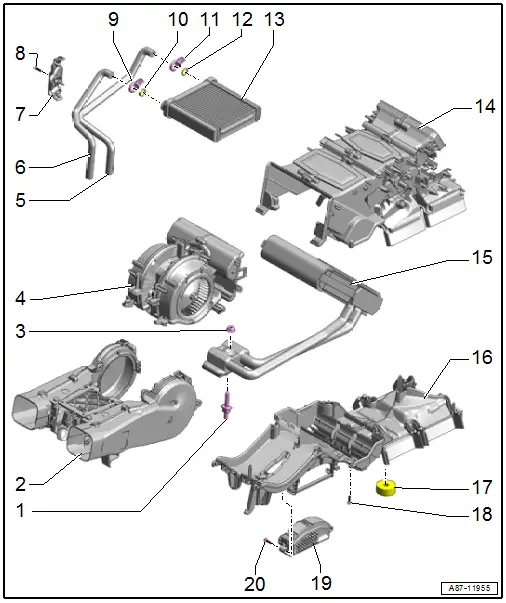
1 - Double Bolt
2 - Air Duct
- With recirculation doors and various levers
- Removing and installing. Refer to → Chapter "Rear Fresh Air Blower -V80-, Removing and Installing".
3 - Nut
- 20 Nm
4 - Rear Fresh Air Blower -V80-
- Ensure the correct allocation. Refer to the Parts Catalog.
- To check. Refer to Vehicle Diagnostic Tester in the "Guided Fault Finding" function
- Refer to → Chapter "Rear Fresh Air Blower -V80-, Removing and Installing"
5 - Coolant Supply Line
- Incorporation of A/C system into coolant circuit. Refer to → Chapter "Rear Heating and A/C system, Incorporation in the Coolant Circuit, High A/C System".
- Removing and installing. Refer to → Chapter "Heater Core, Removing and Installing".
6 - Coolant Return Line
- Incorporating the heating and A/C system in the coolant circuit. Refer to → Chapter "Rear Heating and A/C system, Incorporation in the Coolant Circuit, High A/C System".
- Refer to → Chapter "Heater Core, Removing and Installing".
 Note
Note
The rear heat exchanger remains installed when removing the rear heater and A/C unit and heater and A/C unit. So that the coolant lines must not be removed, disconnect them from the heat exchanger. Refer to → Chapter "Heater and A/C Unit, Removing and Installing, High A/C System".
7 - Bracket for Coolant Pipes
- Removed during removal of the heater and A/C unit (so that the heater core can be removed). Refer to → Chapter "Heater and A/C Unit, Removing and Installing, High A/C System".
8 - Bolt
- 2 Nm
9 - Screw-Type Clamp
- Replace after removing. Refer to the Parts Catalog.
- Removing from the heater core and installing. Refer to → Chapter "Heater Core, Removing and Installing".
10 - O-Ring Seal
- Replacing. Refer to the Parts Catalog.
- Lubricate lightly with coolant before installation.
11 - Screw-Type Clamp
- Replace after removing. Refer to the Parts Catalog.
- Removing from the heater core and installing. Refer to → Chapter "Heater Core, Removing and Installing".
12 - O-Ring Seal
- Replacing. Refer to the Parts Catalog.
- Lubricate lightly with coolant before installation.
13 - Rear Heater Core
- The bonded foam seal must not be damaged and must be bonded
- Removing and installing. Refer to → Chapter "Heater Core, Removing and Installing".
14 - Air Intake Housing Upper Section
- Removing and installing. Refer to → Chapter "Heater and A/C Unit, Removing and Installing, High A/C System".
15 - Evaporator (with Refrigerant Lines)
- Check the glued-on foam seal. It must not be damaged and must be properly bonded.
- Removing and installing. Refer to → Chapter "Evaporator, Removing and Installing".
16 - Air Intake Housing Lower Section
- Removing and installing. Refer to → Chapter "Heater and A/C Unit, Removing and Installing, High A/C System".
17 - Foam Seal
- pushed on the condensation water drain and on the rear fresh air blower drain
18 - Bolt
- 2 Nm
- Quantity: 9
19 - Rear Fresh Air Blower Control Module -J391-
- Ensure the correct allocation. Refer to the Parts Catalog.
- To check. Refer to Vehicle Diagnostic Tester in the "Guided Fault Finding" function
- Refer to → Chapter "Fresh Air Blower Control Module, Removing and Installing "
20 - Bolt
- 2 Nm

