Audi Q7: Evaporator, Removing and Installing
 Note
Note
The removed evaporator contains refrigerant oil that must be returned to the refrigerant circuit (with the new evaporator). Refer to → Refrigerant R134a Servicing; Rep. Gr.87; Refrigerant Circuit Components, Replacing.
Removing
- Remove the rear heater and A/C unit. Refer to → Chapter "Heater and A/C Unit, Removing and Installing, High A/C System".
- Disconnect the connector -B- and free up the wiring harness -A-.
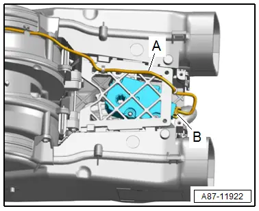
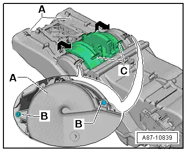
- Remove the bolts -B-.
- Pry up the air duct -A- in the area of the rear fresh air blower -C- and remove in the direction of -arrow-.
- Remove the heater core. Refer to → Chapter "Heater Core, Removing and Installing".
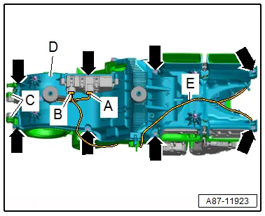
- Disconnect the connectors -A and B- and free up the wiring harness -E-.
- Remove the bolts -arrows-.
- Release the catches -C-.
- Carefully remove the air distribution housing lower section -D- at the same time guide the wiring harness for the rear fresh air blower through the opening.
 Caution
Do not grasp fan wheel of Rear Fresh Air Blower -V80-, force against the fan wheel or shifting the balancing weights fastened to fan wheel may cause imbalance and then problems during operation.
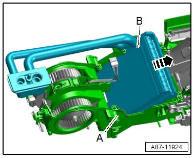
- Remove the evaporator -B- from the air distribution housing upper section -A- in direction of -arrow-.
Installing
Install in reverse order of removal. Note the following:
 Note
Note
- The removed evaporator contains refrigerant oil that must be returned to the refrigerant circuit (with the new evaporator). Refer to → Refrigerant R134a Servicing; Rep. Gr.87; Refrigerant Circuit Components, Replacing.
- Foam seals which have not yet adapted to the sealing surfaces of the air intake housing are present on new evaporator. Therefore these seals must be pushed in with more force.
- If the Rear Fresh Air Blower -V80- and the evaporator should be replaces at the same time, first install the Rear Fresh Air Blower -V80- on the air intake housing, then replace the evaporator.
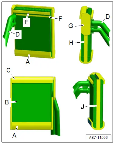
- Check on the evaporator -B- and attached foam seals -A, C, E, F, G, H and J- for damage and correct seating.
- Check foam seals -D- attached to the refrigerant lines for damage and proper adhesion.
- Check the contact surface all around the bevel on the air intake manifold lower section for damage.
 Note
Note
- If the foam seal or the a contact surface / bevel is damaged air can escape and noises can occur when operating the A/C system, fill the damaged area, for example with a silicone adhesive D176 001 A3. Refer to the Parts Catalog.
- If the air distribution housing and the Rear Fresh Air Blower -V80--K- are not correctly joined, air can escape at the connection point and noises can occur when operating the A/C system.
- If a foam seal is damaged, replace it. Refer to the Parts Catalog.
- Check both connections at the refrigerant lines to the evaporator for contamination and damage.
 Note
Note
Even slight damage (a scratch) or a little bit of dirt (a hair) can cause leakage at a connection.
- Evacuate and charge the refrigerant circuit. Refer to → Refrigerant R134a Servicing; Rep. Gr.87; Refrigerant Circuit.
- Perform the basic setting and the output diagnostic test mode of the A/C system. Refer to Vehicle Diagnostic Tester in the "Guided Fault Finding" function.
 Note
Note
- In this vehicle, the actuators are equipped with electronics. During the basic setting, a new actuator learns its position on the heater and A/C unit and can then be activated by the Rear A/C Display Control Head -E265- / the Front A/C Display Control Head -E87- (currently all actuators are identical). Refer to Vehicle Diagnostic Tester in the "Guided Fault Finding" function.
- During the basic setting, the actuators are assigned and adapted corresponding to the switching sequence of the wiring. If this sequence does not conform with the specification, the actuators will adapt incorrectly and the door control will be wrong. Refer to → Chapter "Main Wiring Diagram for A/C System Actuators".
- Check the DTC memory of the Front A/C Display Control Head -E87- (and the Rear A/C Display Control Head -E265-) and if necessary erase any malfunctions shown. Refer to Vehicle Diagnostic Tester in the "Guided Fault Finding" function.
- Operate the A/C system after charging the refrigerant circuit. Refer to → Chapter "A/C System, Starting after Charging Refrigerant Circuit".
 Note
Note
Note the information regarding operating the A/C system after filling. Refer to → Refrigerant R134a Servicing; Rep. Gr.87; A/C System, General Information.
- Check the functionality of the A/C system. Refer to Vehicle Diagnostic Tester in the "Guided Fault Finding" function.

