Audi Q7: Contact Surface Cleaning Set -VAS6410-
Contact Surface Cleaning Set -VAS6410-, Using
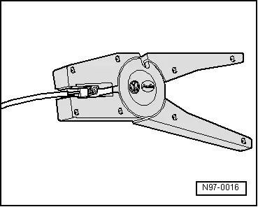
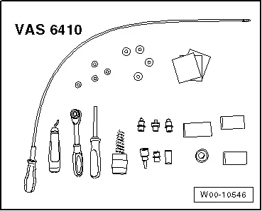
The Contact Surface Cleaning Set -VAS6410- makes optimal repair quality possible in the realm of vehicle electronics. Using the tools, service work can be performed in the area of the contact sensor on the threaded connection wiring harnesses in the high current circuit (starter and charging current). The Contact Surface Cleaning Set -VAS6410- is adapted to the vehicle structural measurements and ensures correct servicing and a comfortable procedure.
 Note
Note
The illustrations of the service work only serve as examples.
Contact Surface Cleaning Set -VAS6410-

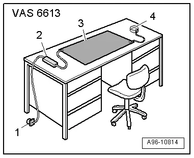
ESD Work Surface -VAS6613-
ESD Work Surface -VAS6613-, Using
- The electro-static discharge ESD Work Surface -VAS6613- protect electronic components from getting damaged by an electro-static charge.
- This makes is possible to perform repairs on sensitive electronic components on an open mat.
- For more information as to what work can be performed on the ESD Work Surface -VAS6613-. Refer to the "Electrical Equipment" chapter in the repair manual.
- Place the electro-static discharge mat -3- from ESD Work Surface -VAS6613- on a clean, dry table.
- Connect the Ground (GND) -2- to one of the buttons on the mat.
- Connect the GND connector adapter -1- to the adapter connector on an outlet with contact protection or connect the alligator clip to a ground in the building or a water pipe.
- Connect the wrist strap -4- to one of the buttons on the mat.
- Attach the wrist strap directly to your wrist - never to your shirt sleeve or jacket sleeve.
 Caution
If working on especially sensitive electronic component and with the pad exposed, use only non-magnetic tools, for example, a Wrench - Driver -T10072-.
Special Tools
Special tools and workshop equipment required
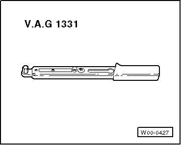
- Torque Wrench 1331 5-50Nm -VAG1331-
- Wiring Harness Repair Set -VAS1978A-
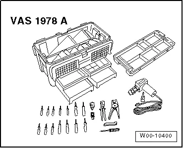
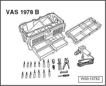
- Wiring Harness Repair Set -VAS1978B-

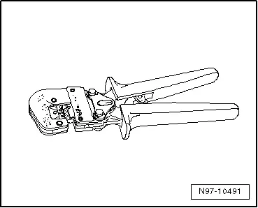
- Adjust the sliding stop in the Wiring Harness Repair Set - Wire Strippers -VAS1978/3- pliers jaws to 12 to 14 mm for the wire to be stripped.
- To press the crimp connector, use the Wiring Harness Repair - Crimping Plier - Base Tool -VAS1978/1-2- with Wiring Harness Repair - Crimping Head - .35-2.5mm -VAS1978/1-1-.
- Wiring Harness Repair Set - Hot Air Blower -VAS1978/14A- from the Wiring Harness Repair Set -VAS1978B-
- Wiring Harness Repair - Blower - Shrink Element -VAS1978/15A- from the Wiring Harness Repair Set -VAS1978B-
- Wiring Harness Repair Set VAS 631 003 -VAS631003-
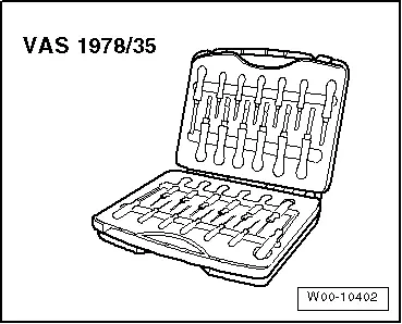
- Release Tool Set -VAS1978/35-
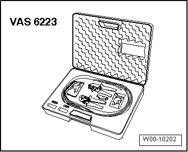
- Fiber Optic Repair Set -VAS6223B-
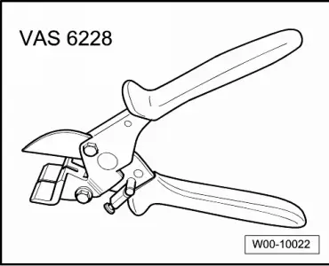
- Hose Cutting Pliers -VAS6228-
- Contact Surface Cleaning Set -VAS6410-
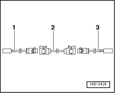
- -1- Adapter wire, for connection to radio; length: approximately 30 cm
- -2- Connecting wire, available in various lengths
- -3- Adapter wire, for connection to antenna; length: approximately 30 cm
- Contact Surface Cleaning Set -VAS6410-
- Aerial Cable Repair Set -VAS6720-
- Wiring Harness Repair - Blower - Shrink Element -VAS1978/15A- from the Wiring Harness Repair Set -VAS1978B-
- Wiring Harness Repair Set -VAS631001-
Revision History
DRUCK NUMBER: A005AA00421