Audi Q7: Overview - Suspension Strut and Upper Control Arm
Overview - Suspension Strut and Upper Control Arm
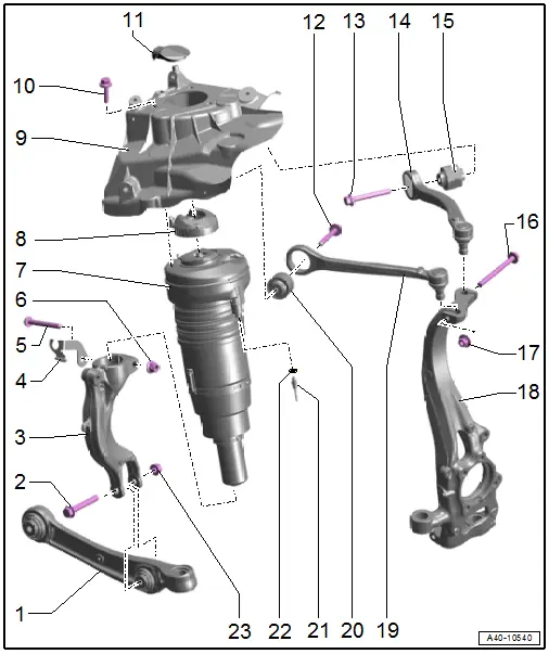
1 - Control Arm
2 - Bolt
- Replace after removing
3 - Shock Absorber Fork
- Removing and installing. Refer to → Chapter "Shock Absorber Fork, Removing and Installing".
4 - Bracket
- For brake hose
5 - Bolt
- Replace after removing
6 - Nut
- 40 Nm +180º
- Replace after removing
- Tighten either in the curb weight position (refer to → Chapter "Wheel Bearing in Curb Weight Position, Lifting Vehicles with Coil Spring") or at the standard vehicle height (refer to → Chapter "Wheel Bearing at Standard Vehicle Height, Lifting Vehicles with Air Suspension").
7 - Suspension Strut
- Shown: for versions with air suspension
- Overview - Suspension Strut Coil Spring. Refer to → Chapter "Overview - Suspension Strut Coil Spring".
- Overview - Air Suspension Strut. Refer to → Chapter "Overview - Air Suspension Strut".
- Installation position. Refer to → Fig. "Installation Position Air Spring Suspension Strut".
8 - Cap
9 - Suspension Strut Tower
10 - Bolt
- Tightening Specifications
- M8x28 bolt with collar: 20 Nm +45º
- M8x32 self-locking bolt with washer: 20 Nm +90º
- Different versions depending on the vehicle. Refer to the Parts Catalog.
- Replace after removing
- Threaded holes for the self-locking bolts must be cleaned, for example, with a thread tap
11 - Cover
- For the connector
- For versions with air suspension
12 - Bolt
- 50 Nm +90º
- Replace after removing
- Tighten either in the curb weight position (refer to → Chapter "Wheel Bearing in Curb Weight Position, Lifting Vehicles with Coil Spring") or at the standard vehicle height (refer to → Chapter "Wheel Bearing at Standard Vehicle Height, Lifting Vehicles with Air Suspension").
13 - Bolt
- 50 Nm +90º
- Replace after removing
- Tighten either in the curb weight position (refer to → Chapter "Wheel Bearing in Curb Weight Position, Lifting Vehicles with Coil Spring") or at the standard vehicle height (refer to → Chapter "Wheel Bearing at Standard Vehicle Height, Lifting Vehicles with Air Suspension").
14 - Upper Rear Control Arm
- Removing and installing. Refer to → Chapter "Upper Control Arm, Removing and Installing".
15 - Bonded Rubber Bushing
- Replacing. Refer to → Chapter "Upper Control Arm Bearing, Replacing".
16 - Bolt
- Replace after removing
17 - Nut
- 40 Nm
- Replace after removing
18 - Wheel Bearing Housing
19 - Upper Front Control Arm
- Removing and installing. Refer to → Chapter "Upper Control Arm, Removing and Installing".
20 - Bonded Rubber Bushing
- Replacing. Refer to → Chapter "Upper Control Arm Bearing, Replacing".
21 - Air Line
- Do not loosen the residual pressure valve
- Tightening specification. Refer to -item 5-
22 - O-Ring
- If sealing ring is leaking nip open and replace.
23 - Nut
- 40 Nm +180º
- Replace after removing
- Tighten either in the curb weight position (refer to → Chapter "Wheel Bearing in Curb Weight Position, Lifting Vehicles with Coil Spring") or at the standard vehicle height (refer to → Chapter "Wheel Bearing at Standard Vehicle Height, Lifting Vehicles with Air Suspension").
Overview - Suspension Strut Coil Spring
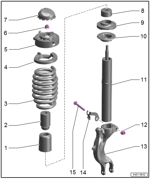
1 - Protective Cover
2 - Stop Buffer
3 - Coil Spring
4 - Spring Support
5 - Strut Mount
- Installation position. Refer to → Fig. "Suspension Strut Coil Spring Installation Position".
6 - Nut
- 50 Nm
- Replace after removing
7 - Cap
- Installation position. Refer to → Fig. "Coil Spring Cap Installation Position".
8 - Protective Cap
9 - Backing Plate
10 - Lower Spring Plate
11 - Shock Absorber
- Because of different shock absorber valve systems, only install new shock absorbers from the same manufacturer on both axles, if possible.
- Removing and installing. Refer to → Chapter "Suspension Strut, Servicing".
12 - Nut
- Tightening specification. Refer to -item 6-
13 - Shock Absorber Fork
- Removing and installing. Refer to → Chapter "Shock Absorber Fork, Removing and Installing".
14 - Bracket
- For brake hose
15 - Bolt
- Replace after removing
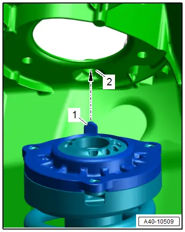
Suspension Strut Coil Spring Installation Position
- The strut mount positioning pin -1- must engage in the hole -2- in the suspension strut tower in direction of -arrow-.
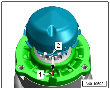
Coil Spring Cap Installation Position
- The opening -2- of the cap must be flush with the strut mount positioning pin -1- in direction of -arrow-.
Overview - Air Suspension Strut
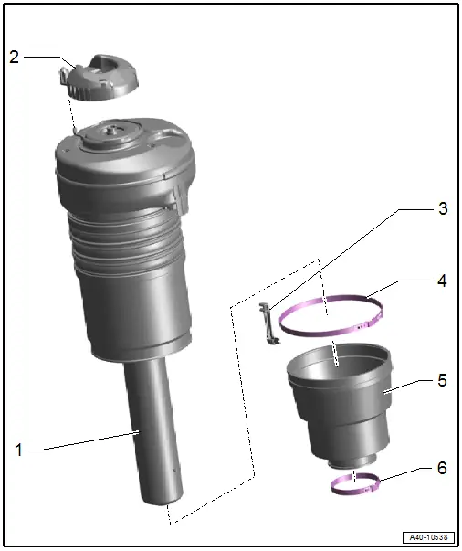
1 - Air Spring Strut
- With the Left Front Damping Adjustment Valve -N336-/Right Front Damping Adjustment Valve -N337-
- If faulty replace the complete valve for the air spring damping adjustment
2 - Cap
- Installation position. Refer to → Fig. "Air Spring Cap Installation Position".
3 - Bracket
- For the air line
- Quantity: 2
- Installation position. Refer to → Fig. "Air Line Bracket Installation Position".
4 - Clamp
- Replace after removing
- Installation position. Refer to → Fig. "Clamp Installation Position".
- Tensioning. Refer to → Fig. "Tension the Clamp on the Air Spring.".
5 - Boot
- Must not have any pressure marks; correct any pressure marks by hand.
- Push upward over the collars on the suspension strut housing
- Replacing. Refer to → Chapter "Boot, Replacing".
- Installation position. Refer to → Fig. "Boot Installation Position".
6 - Clamp
- Replace after removing
- Installation position. Refer to → Fig. "Clamp Installation Position".
- Tensioning. Refer to → Fig. "Tension the Clamp on the Air Spring.".
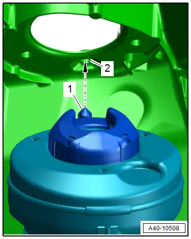
Installation Position Air Spring Suspension Strut
- The cap positioning pin -1- must engage in the hole -2- in the suspension strut tower in direction of -arrow-.
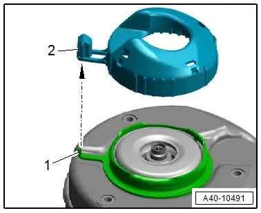
Air Spring Cap Installation Position
- The suspension strut positioning pin -1- must engage in the cap -2- in direction of -arrow-.
- Push in the cap until it engages audibly.
Air Line Bracket Installation Position
- Position the bracket -1- over the pointed protrusion -arrow- on the clamp -2 -as shown.
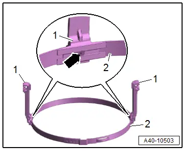
Clamp Installation Position
- The clamping ears -arrows- of the clamps -1 and 2- must align with the residual pressure valve -3- as shown.
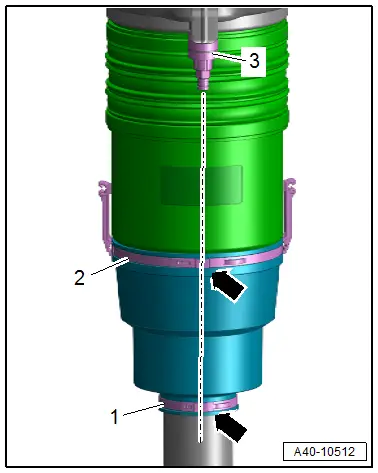
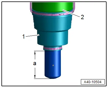
Boot Installation Position
- Push the boot -1- upward over the collars on the suspension strut housing -2-.
- Pay attention to the lower dimension -a-.
- Dimension -a- = 96 mm.
Tension the Clamp on the Air Spring.
- Before tensioning the clamp pay attention to their installation position. Refer to → Fig. "Air Line Bracket Installation Position" and → Fig. "Clamp Installation Position".
- To tension the lower clamp press the front wheels accordingly.
- To tension the upper clamp lift the wheel bearing into the standard vehicle height. Refer to → Chapter "Wheel Bearing at Standard Vehicle Height, Lifting Vehicles with Air Suspension".
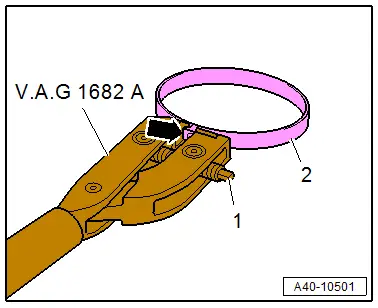
- Attach the Clampling Pliers -VAG1682A- as shown. When doing that, make sure the jaws on the pliers are centered -arrow- on the clamping sleeve -2-.
 Note
Note
- Make sure the threads on the spindle on the pliers move easily. Lubricate with MoS2 grease, if necessary.
- If difficult to tighten, for example because of dirty threads, the proper clamping force of the clamping sleeve will not be reached even when tightened to the specification.
- Tension the clamp by turning the spindle -1- with the torque wrench, at the same time do not tilt the pliers.
- Tightening specification: 8 Nm.
Overview - Tower Brace
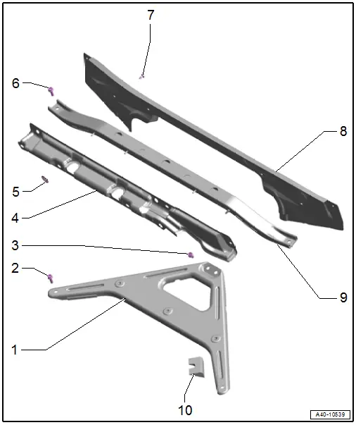
1 - Tower Brace
- Removing and installing. Refer to → Chapter "Tower Brace, Removing and Installing".
2 - Bolt
- 25 Nm
3 - Bolt
- 25 Nm
4 - Trim Panel
5 - Lock Washer
6 - Bolt
- 25 Nm
7 - Bolt
- Tightening specification. Refer to → Body Exterior; Rep. Gr.50; Bulkhead; Overview - Bulkhead.
8 - Plenum Chamber End Plate
9 - Additional Reinforcement
- For the tower brace
- Removing and installing. Refer to → Chapter "Tower Brace, Removing and Installing".
10 - Sealing Piece

