Audi Q7: Fan Shroud, Removing and Installing
Special tools and workshop equipment required
- Coolant Collection System -VAS5014- or Shop Crane - Drip Tray -VAS6208-
 Caution
This procedure contains mandatory replaceable parts. Refer to component overview prior to starting procedure.
Mandatory Replacement Parts
- O-rings - Left and right lower coolant hoses
- O-ring - Top coolant hose
Removing
 WARNING
There is a risk of injury if the radiator fan turns on by itself.
Disconnect the connectors before working near the fan shroud.
- Remove the front noise insulation. Refer to → Body Exterior; Rep. Gr.66; Noise Insulation; Noise Insulation, Removing and Installing.
- Place the container of the Coolant Collection System -VAS5014- or the Shop Crane - Drip Tray -VAS6208- underneath.
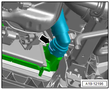
- Lift the clamp -arrow- and remove the coolant hose from the lower right of the radiator and drain the coolant.
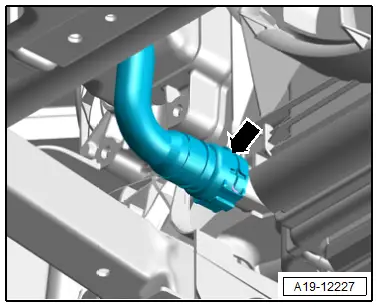
- Lift the clamp -arrow- and remove the coolant hose from the lower left of the radiator and drain the coolant.
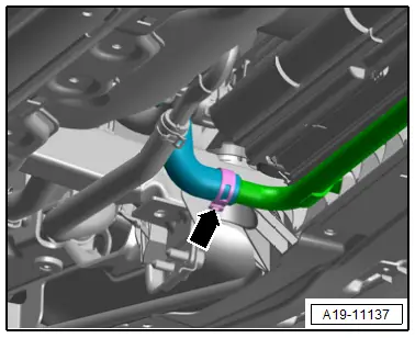
Versions with Side Auxiliary Cooler:
- If installed, loosen the hose clamp -arrow- and remove the coolant hose.
- Remove the lower left longitudinal member. Refer to → Body Exterior; Rep. Gr.50; Lock Carrier; Overview - Lock Carrier.
Continuation for All Vehicles:
- Remove the front left coolant pipes. Refer to → Chapter "Front Left Coolant Pipes, Removing and Installing".
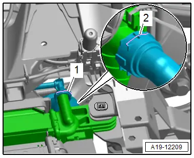
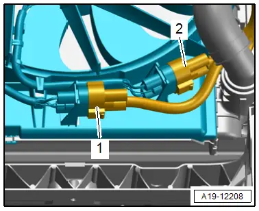
- Lift the clip -2- and remove the connection from the radiator and move to the side
 Note
Note
Ignore -1-.
- Disconnect the connectors -1 and 2- for the radiator fan.
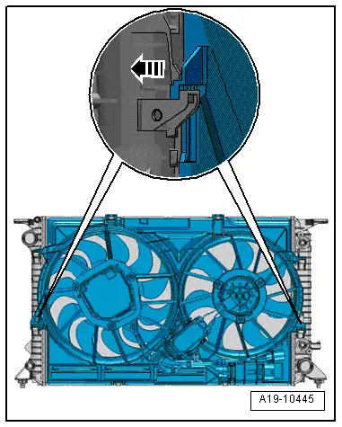
- Push the left and right locking latches for the fan shroud at the same time in direction of -arrow- and lift the fan shroud upward from the radiator and remove from underneath.
Installing
Install in reverse order of removal and note the following:
- Install the left front coolant pipes. Refer to → Chapter "Front Left Coolant Pipes, Removing and Installing".
- Connections and wire routing. Refer to → Wiring diagrams, Troubleshooting & Component locations.
- Connect the coolant hose to the connector coupling. Refer to → Fig. "Connect the Coolant Hose to the Connector Coupling".
 Note
Note
Used coolant cannot be used again.
- Fill with coolant.
Tightening Specifications
- Refer to → Chapter "Overview - Radiator/Radiator Fan"
- Refer to → Chapter "Overview - Charge Air Hose Connections"
- Refer to → Body Exterior; Rep. Gr.50; Lock Carrier; Overview - Lock Carrier.
- Refer to → Body Exterior; Rep. Gr.66; Noise Insulation; Overview - Noise Insulation.
Radiator Fan, Removing and Installing
Removing
 Note
Note
Install all the cable ties back in their original locations.
- Remove the fan shroud. Refer to → Chapter "Fan Shroud, Removing and Installing".
- Free up the wiring harness.
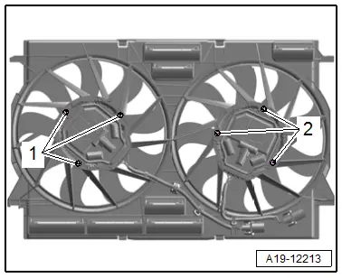
- Remove the bolts -1 or 2- and remove the corresponding radiator fan.
 Caution
Risk of noises due to an imbalanced fan wheel.
Do not remove the counter-balancing clamps from the fan wheel.
Installing
Install in reverse order of removal and note the following:
- Install the fan shroud. Refer to → Chapter "Fan Shroud, Removing and Installing".
Tightening Specifications
- Refer to → Chapter "Overview - Radiator/Radiator Fan"
Radiator Shutter, Removing and Installing
Removing
- Remove the headlamps. Refer to → Electrical Equipment; Rep. Gr.94; Headlamps; Headlamp, Removing and Installing.
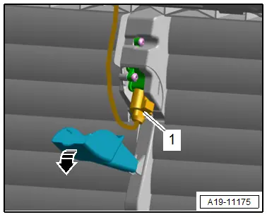
- Open the cover in direction of -arrow- and disconnect the connector -1- on the Radiator Shutter Motor -V544- and free up the wire.
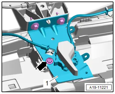
- Remove the bolts -arrows- and move the mounting bracket with release cable for the hook operating lever -1-.
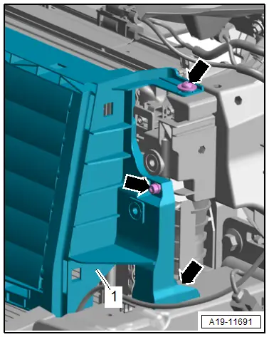
- Open the catches in direction of -arrows- and remove the air duct -1-.
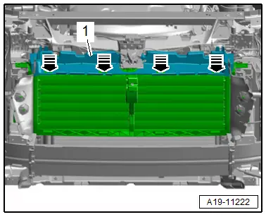
- Remove the bolts -arrows-.
- Free up the wiring harness.
- Remove the radiator shutter -1-.
Installing
Install in reverse order of removal and note the following:
- Install the headlamps. Refer to → Electrical Equipment; Rep. Gr.94; Headlamps; Headlamp, Removing and Installing.
Tightening Specifications
- Refer to → Chapter "Overview - Radiator/Radiator Fan"
- Refer to → Body Exterior; Rep. Gr.55; Hood; Overview - Release Cable.

