Audi Q7: Crankshaft
Overview - Crankshaft
 Note
Note
For assembly work, secure the engine on the Engine and Gearbox Bracket VAS6095A -VAS6095A-. Refer to → Chapter "Engine, Securing to Engine and Transmission Holder".
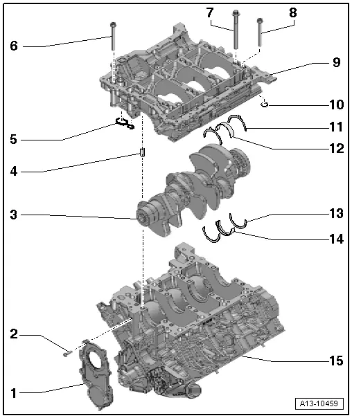
1 - Sealing Flange, Belt Pulley Side
- Replacing. Refer to → Chapter "Sealing Flange, Removing and Installing, Belt Pulley Side".
2 - Bolt
- Tightening specification and sequence. Refer to → Fig. "Ribbed Belt Pulley Side Sealing Flange - Tightening Specifications and Sequence".
3 - Crankshaft
- Axial play, measuring. Refer to → Chapter "Crankshaft, Measuring Axial Clearance".
- Radial play, measuring. Refer to → Chapter "Crankshaft, Measuring Radial Clearance".
- Crankshaft dimensions. Refer to → Chapter "Crankshaft Dimensions".
4 - Alignment Sleeve
- Quantity: 4
- Insert into guide frame. Refer to → Fig. "Sealant Application for Guide Frame, Position of Alignment Sleeves"
5 - Seal
- Replace after removing
6 - Bolt
- Tightening specification and sequence. Refer to → Fig. "Guide Frame, Installing".
- For guide frame to cylinder block sealing surfaces
- There are different bolt lengths and bolt heads
7 - Bolt
- Tightening specification and sequence. Refer to → Fig. "Guide Frame, Installing".
- Replace after removing
- Long, large collar
- For inner row of guide frame
- Use old bolts for the radial clearance measurement
8 - Bolt
- Tightening specification and sequence. Refer to → Fig. "Guide Frame, Installing".
- Short, small collar
- For outer row of guide frame
9 - Guide Frame
- With Oil Pressure Regulation Valve -N428-. Refer to → Fig. " Oil Pressure Regulation Valve -N428- "
- To remove, remove the glide rail -item 1- for the timing mechanism drive chain
- Sealant application. Refer to → Fig. "Sealant Application for Guide Frame, Position of Alignment Sleeves"
- Oil Pressure Regulation Valve -N428-, Removing and installing. Refer to → Chapter "Oil Pressure Regulation Valve -N428-, Removing and Installing".
10 - Gasket
- Replace after removing
11 - Thrust Washer
- Only crankshaft bearing 3
- Installation position: the oil groove faces outward
- Note installation position in the guide frame
12 - Bearing Shell
- For guide frame without oil groove
- Replace any worn bearing shells
- Note the installation position
- Insert new guide frame bearing shells with the correct color coding. Refer to → Fig. "Crankshaft Bearing Shell Allocation for Guide Frame"
13 - Thrust Washer
- Only crankshaft bearing 3
- Installation position: the oil groove faces outward
- Pay attention to the installation position in the cylinder block
14 - Bearing Shell
- For cylinder block with oil groove
- Replace any worn bearing shells
- Note the installation position
- Insert new cylinder block bearing shells with the correct color coding. Refer to → Fig. "Crankshaft Bearing Shell Allocation for Cylinder Block"
15 - Cylinder Block
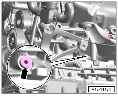
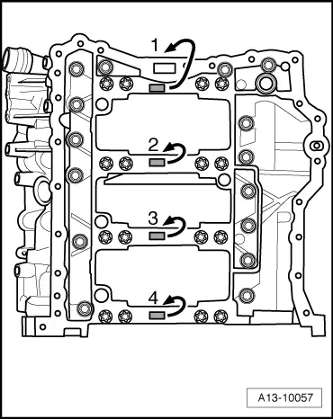
"TDC" Marking Plug - Tightening Specification
 Note
Note
Replace the O-ring after removing.
- Tighten the plug -arrow- to 14 Nm.
Oil Pressure Regulation Valve -N428-
1 - Connector
2 - Replace the O-ring after removing
3 - Bolt, 9 Nm
4 - Oil Pressure Regulation Valve -N428-
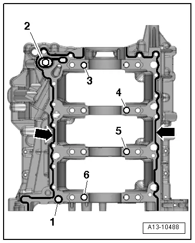
Sealant Application for Guide Frame, Position of Alignment Sleeves
- Clean any oil or grease off the sealing surfaces.
- Apply the sealant beads -arrows- on the clean sealing surfaces of the guide frame as shown.
- The groove on the sealing surface must be completely filled with sealant.
- The sealant beads must be 1.5 to 2.0 mm above the sealing surface.
- Position the seals -1 and 2-.
- Check if the alignment sleeves -3 through 6- are inserted at the locations in the guide frame as shown.
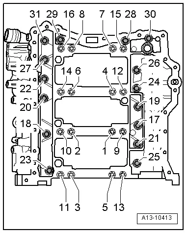
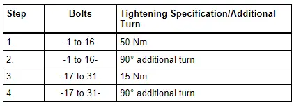
Guide Frame, Installing
 Note
Note
Replace the bolts that were tightened with an additional turn after removing them.
- Insert the long bolts in the inner row of the guide frame.
- Tighten the bolts in the steps of the sequence shown:
Crankshaft Bearing Shell Allocation for Cylinder Block
- Bearing shells with the correct thickness are allocated to the cylinder block in the factory. The colored dots on the sides of the bearing shell mark the bearing shell thickness.
- Allocation of bearing shells to the cylinder block is marked by a letter on the respective bearing on the guide frame.
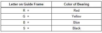
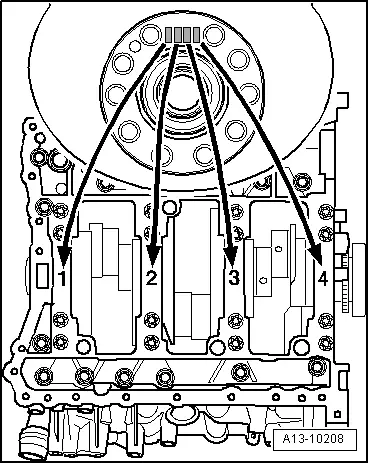
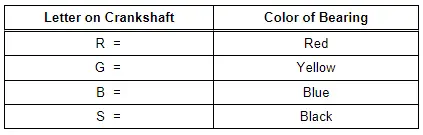
Crankshaft Bearing Shell Allocation for Guide Frame
- Bearing shells with the correct thickness are allocated to the guide frame in the factory. The colored dots on the sides of the bearing shell mark the bearing shell thickness.
- Allocation of bearing shells to the guide frame is marked on the transmission flange of the crankshaft by a row of letters. The first letter of the row represents bearing "1", the second letter is for bearing "2", etc.
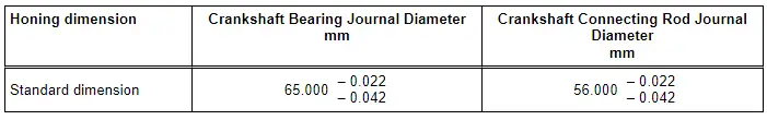
Crankshaft Dimensions
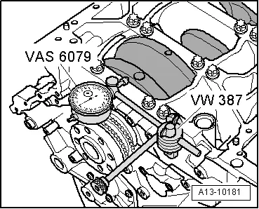
Crankshaft, Measuring Axial Clearance
Special tools and workshop equipment required
- Dial Gauge Holder -VW387-
- Dial Gauge - 0-10mm -VAS6079-
Procedure
- Install the Dial Gauge - 0-10mm -VAS6079- with the Dial Gauge Holder -VW387- on the cylinder block as shown.
- Place the dial gauge against the crankshaft counterweight.
- Press the crankshaft against the dial gauge by hand and set the dial gauge to "0".
- Press the crankshaft off the dial gauge and read the measurement.
- Axial clearance: 0.15 to 0.25 mm.
Crankshaft, Measuring Radial Clearance
Special tools and workshop equipment required
- Plastigage
Procedure
 Note
Note
Use old bolts to measure radial clearance measurement.
- Remove the guide frame and clean the bearing journal.
- Place the Plastigage over the entire width of the bearing journal or into the bearing shells.
- The Plastigage must rest in the center of the bearing shell.
- Position the guide frame and tighten using the old bolts. Refer to → Fig. "Guide Frame, Installing". Do not turn the crankshaft while doing so.
- Remove the guide frame again.
- Compare the width of the Plastigage with the measuring scale.
Radial clearance:
- New: 0.015 to 0.055 mm.
- Wear limit: 0.080 mm.
- Replace the bolts for the final assembly.
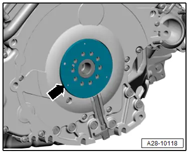
Sensor Wheel, Removing and Installing
Removing
- The transmission is removed. Refer to → 8-Speed Automatic Transmission 0D5; Rep. Gr.37; Transmission, Removing and Installing; Transmission, Removing.
- Remove the drive plate. Refer to → Chapter "Drive Plate, Removing and Installing".
- Remove the sensor wheel -arrow-.
Installing
Install in reverse order of removal and note the following:
- Install the drive plate. Refer to → Chapter "Drive Plate, Removing and Installing".
Sensor Wheel, Checking
 Caution
There is a risk of destroying the sensor wheel by magnetic force.
- Do not place the sensor wheel near magnets (for example lamp base, speakers).
- If the drive plate/flywheel or the sensor wheel itself was removed or replaced, the sensor wheel function must be checked before installing. Refer to → Chapter "Sensor Wheel, Checking".
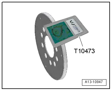
Special tools and workshop equipment required
- Gauge - Sender Wheel -T10473-
Procedure
- Sensor wheel removed.
- Check the entire circumference of the sensor wheel with the Gauge - Sender Wheel -T10473- as shown.
Sensor wheel test diagram
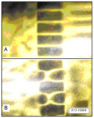
A - Sensor Wheel OK
B - Sensor Wheel Faulty

