Audi Q7: Cylinder Block, Transmission Side
Overview - Cylinder Block, Transmission Side
![]() Note
Note
For assembly work, secure the engine on the Engine and Gearbox Bracket -VAS6095A-. Refer to → Chapter "Engine, Securing to Engine and Transmission Holder".
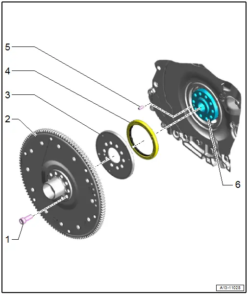
1 - Bolt
- 60 Nm +90º
- Replace after removing
2 - Drive Plate
- With the bearing flange
- Check the contact surfaces on the bearing flange and the torque converter holes for cracks and wear grooves.
- Removing and installing. Refer to → Chapter "Drive Plate, Removing and Installing".
3 - Sensor Wheel
- For the Engine Speed Sensor -G28-
- Removing and installing. Refer to → Chapter "Sensor Wheel, Removing and Installing".
- Checking using the Vehicle Diagnostic Tester. Refer to → Chapter "Sensor Wheel, Checking".
4 - Gasket
- For the crankshaft on the transmission side
- Replacing. Refer to → Chapter "Crankshaft Seal, Replacing, Transmission Side".
5 - Alignment Pin
6 - Crankshaft
Drive Plate, Removing and Installing
Special tools and workshop equipment required
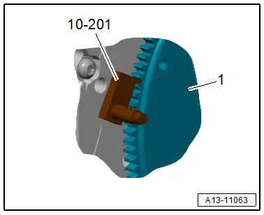
- Counterhold - Flywheel -10-201-
![]() Caution
Caution
This procedure contains mandatory replaceable parts. Refer to component overview prior to starting procedure.
Mandatory Replacement Parts
- Bolts - Drive plate
Removing
- The transmission is removed. Refer to → 8-Speed Automatic Transmission 0D5; Rep. Gr.37; Transmission, Removing and Installing; Transmission, Removing.
- Insert the Counter Hold Tool -10-201- to loosen the bolts.
![]() Caution
Caution
Risk of damaging the outer surface of the bearing flange at the drive plate.
Use an internal multi-point socket with a shaft that is at least 40 mm long to loosen and tighten the drive plate bolts.
- Remove the bolts, drive plate and sensor wheel.
Installing
Install in reverse order of removal and note the following:
![]() Note
Note
Replace the bolts that were tightened with an additional turn after removing them.
- Pay attention to the alignment pin when installing the drive plate.
- Reposition the Counter Hold Tool -10-201- to tighten the bolts.
Tightening Specifications
- Refer to → Chapter "Overview - Cylinder Block, Transmission Side"
Crankshaft Seal, Replacing, Transmission Side
Special tools and workshop equipment required
- Seal Installer - Crankshaft -T10122A-
- Crank Shaft Seal Installer - Guide Piece -T10122/6-
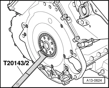
- Puller - Crankshaft/Power Steering Seal -T20143/2-
![]() Caution
Caution
This procedure contains mandatory replaceable parts. Refer to component overview prior to starting procedure.
Mandatory Replacement Parts
- Seal - Crankshaft on the transmission side
Procedure
- The transmission is removed. Refer to → 8-Speed Automatic Transmission 0D5; Rep. Gr.37; Transmission, Removing and Installing; Transmission, Removing.
- Remove the drive plate. Refer to → Chapter "Drive Plate, Removing and Installing".
- Pry out the shaft seal using the Puller - Crankshaft/Power Steering Seal -T20143/2-.
- Clean the contact and sealing surface.
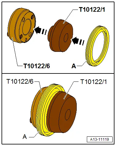
- Attach the Crankshaft Seal Installer Kit - Guide Piece -T10122/1- to the Crankshaft Seal Installer Kit - Guide Piece -T10122/6- and push the shaft seal -A- on the guide piece.
- Remove the Crankshaft Seal Installer Kit - Guide Piece -T10122/1-.
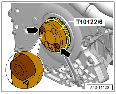
- Position the Crankshaft Seal Installer Kit - Guide Piece -T10122/6- on the crankshaft.
- Attach the Guide Piece to the crankshaft through the mounting points -A- with the bolts -arrows-.
![]() Caution
Caution
There is a risk of leaks due to incorrect assembly.
To prevent the shaft seal sealing lip from rolling onto itself, insert the shaft seal by hand on the crankshaft.
- Push the shaft seal by hand using the Crankshaft Seal Installer Kit - Guide Piece - T10122/6- on the crankshaft.
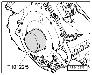
- Press the shaft seal in evenly all around with Crankshaft Seal Installer Kit - Thrust Sleeve -T10122/5-.
- Remove the Crankshaft Seal Installer Kit - Guide Piece -T10122/6-.
- Check the shaft seal as well as its sealing lip for correct seating. If the sealing lip is partially rolled back, repeat the procedure with a new shaft seal.
- Install the drive plate. Refer to → Chapter "Drive Plate, Removing and Installing".