Audi Q7: Fresh Air Intake, Removing and Installing
Overview - Heating and A/C System Front Fresh Air Intake
 Note
Note
Depending on the vehicle version, there are different fresh air intake versions. Refer to the Parts Catalog.
Fresh Air Intake Version "1"
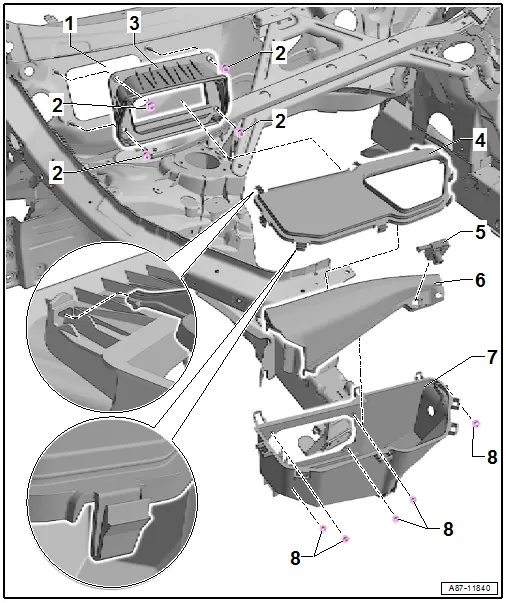
1 - Fresh Air Intake Opening in the Plenum Chamber Rear Panel
2 - Nut
- 3.5 Nm.
- Tighten the nuts in multiple steps in a diagonal sequence to the specified tightening specification
 Note
Note
If the tightening sequence is not followed, water can enter via the sealing surface in the opening for the fresh air intake and then in the air intake shroud of the heater and A/C unit.
3 - Air Intake Box with Seal to Plenum Chamber - Rear Panel
- Check the air intake box and seal for damage and correct assembly before installing
 Note
Note
Check the air intake box and seals before installing for damage, completely replace a damaged seal or the air intake box. Refer to the Parts Catalog.
4 - Outer Cover for the Fresh Air Intake Box (Rain Water Drain Channel)
- Check the outer cover before installing for damage, if the cover is damaged water can enter the air intake shroud for the fresh air intake and thus the heater and A/C unit.
- When installing, ensure it is seated correctly in the fresh air intake. If the fresh air intake is not installed correctly, water can run into the heater and A/C unit air intake shroud.
5 - Humidity Sensor in Fresh Air Intake Duct -G657- / Air Quality Sensor -G238-
- Different versions (with or without Air Quality Sensor -G238-) depending on the version of the A/C system. Refer to the Parts Catalog.
- Removing and installing. Refer to → Chapter "Air Quality Sensor -G238- with the Humidity Sensor In Fresh Air Intake Duct -G657-, Removing and Installing".
- Check the function. Refer to → Chapter "Air Quality Sensor -G238- Function" and use the Vehicle Diagnostic Tester in the "Guided Fault Finding" function.
6 - Fresh Air Intake Inner Cover
- Check the inner cover before installing for damage, if the cover is damaged water can enter the air intake shroud for the fresh air intake and thus the heater and A/C unit.
- When installing, ensure it is seated correctly in the fresh air intake. If the fresh air intake is not installed correctly, water can run into the heater and A/C unit air intake shroud.
7 - Air Intake Box with Water Drain Grommet
- Check the air intake box and water drains for debris, function, damage and correct assembly before installing
- Check the line connection to Humidity Sensor in Fresh Air Intake Duct -G657- / Air Quality Sensor -G238- for correct routing.
 Note
Note
- Check the air intake box and the water drain grommets before installing for damage, completely replace damaged water drain grommets or the air intake box. Refer to the Parts Catalog.
- If the water drain grommet is closed or blocked the water can flow too slowly and the water level can rise to high and water can enter the heater and A/C unit air intake shroud.
- If there is a missing or faulty grommet air can be extracted out of the area under the intake box, which can lead to odors if the plenum chamber is contaminated.
8 - Nut
- 3.5 Nm.
- Tighten the different nuts evenly in multiple steps to the specified tightening specification
 Note
Note
If the tightening sequence is not followed, water can enter the air intake box and then the air intake shroud of the heater and A/C unit.
Fresh Air Intake Version "2"
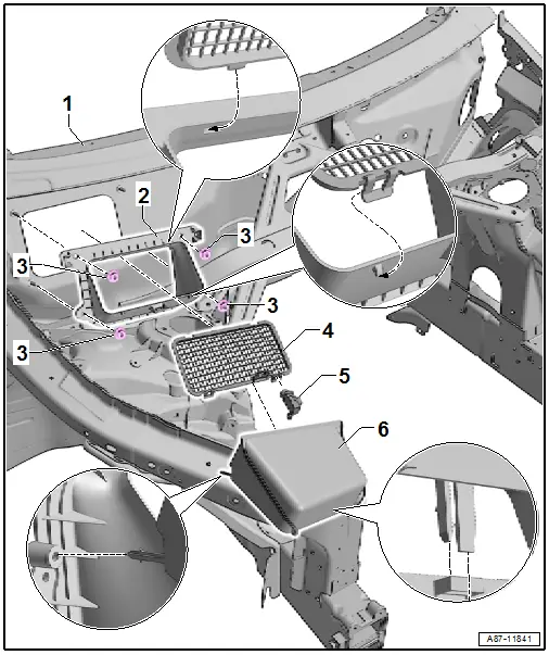
1 - Fresh Air Intake Opening in the Plenum Chamber Rear Panel
2 - Air Intake Box with Seal to Plenum Chamber - Rear Panel
- Check the air intake box and seal for damage and correct assembly before installing
 Note
Note
Check the air intake box and seals before installing for damage, completely replace a damaged seal or the air intake box. Refer to the Parts Catalog.
3 - Nut
- 3.5 Nm.
- Tighten the nuts in multiple steps to the specified tightening specification
 Note
Note
If the tightening sequence is not followed, water can enter via the sealing surface in the opening for the fresh air intake and then in the air intake shroud of the heater and A/C unit.
4 - Debris Grille
5 - Humidity Sensor in Fresh Air Intake Duct -G657- / Air Quality Sensor -G238-
- Different versions (with or without Air Quality Sensor -G238-) depending on the version of the A/C system. Refer to the Parts Catalog.
- Removing and installing. Refer to → Chapter "Air Quality Sensor -G238- with the Humidity Sensor In Fresh Air Intake Duct -G657-, Removing and Installing".
- Check the function. Refer to → Chapter "Air Quality Sensor -G238- Function" and use the Vehicle Diagnostic Tester in the "Guided Fault Finding" function.
6 - Outer Cover for the Fresh Air Intake Box (Rain Water Drain Channel)
- Check the outer cover before installing for damage, if the cover is damaged water can enter the air intake shroud for the fresh air intake and thus the heater and A/C unit.
- When installing, ensure it is seated correctly in the fresh air intake. If the fresh air intake is not installed correctly, water can run into the heater and A/C unit air intake shroud.
Fresh Air Intake, Removing and Installing
Removing
- Turn off the ignition.
- Remove the plenum chamber cover. Refer to → Body Interior; Rep. Gr.50; Bulkhead; Plenum Chamber Cover, Removing and Installing.
- Remove the Air Quality Sensor -G238- (with the Humidity Sensor in Fresh Air intake Duct -G657-). Refer to → Chapter "Air Quality Sensor -G238- with the Humidity Sensor In Fresh Air Intake Duct -G657-, Removing and Installing".
- Remove the air intake shroud according to the installation instructions. Refer to → Chapter "Overview - Heating and A/C System Front Fresh Air Intake".
Installing
Installation is done is reverse order, observe the following:
- Check before installing the components of the fresh air intake, the plenum chamber, and the water drains present for debris and damage if necessary clean these components. Refer to → Chapter "Plenum Chamber Water Drain, Removing and Installing".
- Pay attention to the tightening sequence for the nuts when installing them.
- Install the air intake shroud according to the installation instructions. Refer to → Chapter "Overview - Heating and A/C System Front Fresh Air Intake".
- Tighten the nuts lightly hand-tight. Refer to → Chapter "Overview - Heating and A/C System Front Fresh Air Intake".
 Note
Note
- Check before installing that all components of the fresh air intake and the bonded seal for damage, replace the damaged seal or the corresponding fresh air intake component. Refer to the Parts Catalog.
- If ignored, water can flow over the sealing surface in the air intake shroud of the heater and A/C unit.
- When installing, ensure fresh air intake and accompanying seal are seated correctly. If the fresh air intake is not installed correctly, water can run into the heater and A/C unit air intake shroud.
- Prior to installation, check the plenum chamber cover and the windshield frame for damage. In the case of an incorrectly installed or damaged cover, water can enter fresh air intake duct and thus the heater and A/C unit.
Fresh Air Intake, Checking
Procedure
- Turn off the ignition.
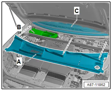
- Remove the plenum chamber cover -A-. Refer to → Body Interior; Rep. Gr.50; Bulkhead; Plenum Chamber Cover, Removing and Installing.
 Note
Note
To prevent water from running via intake shaft -B- into the heater and A/C unit when plenum chamber cover -A- is installed, plenum chamber cover -A- must not be damaged. In addition the plenum chamber cover -A- must be correctly and completely engaged in the windshield frame -C-.
- Check the plenum chamber cover -A- for damage.
- Check the catch on the plenum chamber cover -A- to the windshield frame -C- for damage.
 Note
Note
The locking mechanism of the plenum chamber cover -A- in windshield frame -C- prevents water from running between the frame and the plenum chamber cover into intake shaft -B- of the heater and A/C unit. Refer to → Body Exterior; Rep. Gr.50; Bulkhead; Plenum Chamber Cover, Removing and Installing.