Audi Q7: Electrical Component Locations Overview
Audi Q7 (4M) 2016-2025 Workshop Manual / Chassis / Suspension, Wheels, Steering / Self-Leveling Suspension / Electrical Component Locations Overview
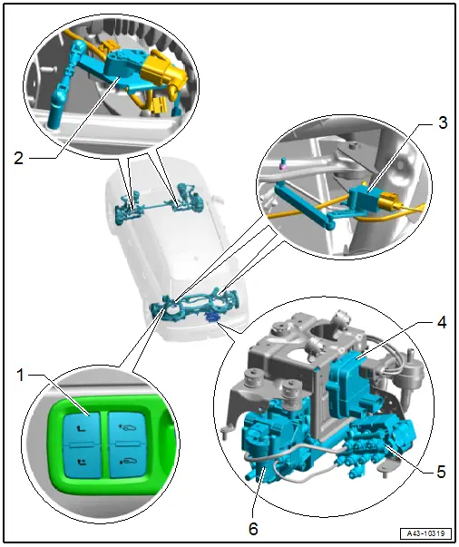
1 - Loading Sill Lowering Control Head -E682-
- With the following integrated components
- Load Level Button -E539-
- Power Pivoting Trailer Hitch Button -E474-, equipment level
- Component Location Overview. Refer to → Electrical Equipment; Rep. Gr.96; Controls; Component Location Overview - Controls in Luggage Compartment
2 - Front Level Control System Sensor
- Left Front Level Control System Sensor -G78-, Right Front Level Control Sensor -G289-
- Overview. Refer to → Chapter "Overview - Front Level Control System Sensor".
3 - Rear Level Control System Sensor
- Left Rear Level Control System Sensor -G76-, Right Rear Level Control System Sensor -G77-
- Overview. Refer to → Chapter "Overview - Rear Level Control System Sensor".
4 - Level Control System Compressor Electronics -J1135-
- Removing and installing. Refer to → Chapter "Level Control System Compressor Electronics -J1135-, Removing and Installing".
5 - Adaptive Suspension Valve Block -NX7-
- With the following integrated components
- Level Control Pressure Sensor -G291-
- Left Front Suspension Strut Valve -N148-
- Right Front Suspension Strut Valve -N149-
- Left Rear Suspension Strut Valve -N150-
- Right Rear Suspension Strut Valve -N151-
- Level Control Accumulator Valve -N311-
- The components cannot be replaced separately
- Is a components is faulty replace the adaptive suspension valve block
- Overview. Refer to → Chapter "Overview - Air Lines".
- 6 - Level Control System Compressor Motor -V66-
- With integrated Level Control System Solenoid -N111-
- The Level Control System Solenoid - N111- cannot be replaced separately, if faulty replace the Level Control System Compressor Motor -V66-
- Overview. Refer to → Chapter "Overview - Air Supply Unit".
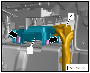
Drivetrain Control Module -J775-
- Component location: under the A/C unit
- Removing and installing. Refer to → Chapter "Drivetrain Control Module -J775-, Removing and Installing".
- Tighten the left and right nuts -arrows- to 8 Nm.
Component Location Overview - Air Suspension
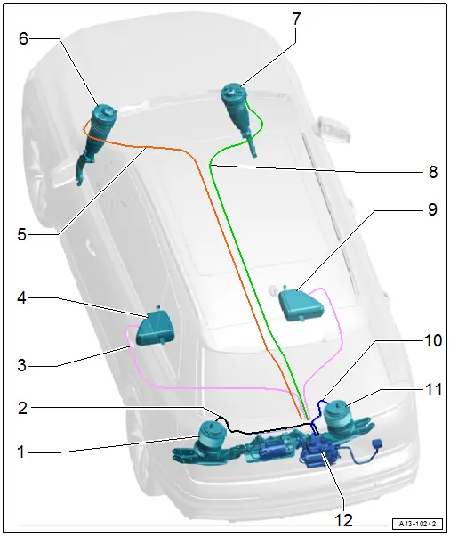
1 - Rear Left Air Spring
- With Left Rear Damping Adjustment Valve -N338-
- Overview. Refer to → Chapter "Overview - Suspension Strut, Shock Absorber and Spring, Air Spring".
2 - "Black" Air Line
3 - "Purple" Air Line
4 - Left Pressure Reservoir
- Under the carpet in the rear left footwell
- Removing and installing. Refer to → Chapter "Pressure Reservoir, Removing and Installing".
5 - "Red" Air Line
6 - Left Front Air Spring
- With Left Front Damping Adjustment Valve -N336-
- Overview. Refer to → Chapter "Overview - Suspension Strut and Upper Control Arm".
7 - Right Front Air Spring
- With Right Front Damping Adjustment Valve -N337-
- Overview. Refer to → Chapter "Overview - Suspension Strut and Upper Control Arm".
8 - "Green" Air Line
9 - Right Pressure Reservoir
- Under the carpet in the rear right footwell
- Removing and installing. Refer to → Chapter "Pressure Reservoir, Removing and Installing".
10 - "Blue" Air Line
11 - Rear Right Air Spring
- With Right Rear Damping Adjustment Valve -N339-
- Overview. Refer to → Chapter "Overview - Suspension Strut, Shock Absorber and Spring, Air Spring".
12 - Air Supply Unit with Level Control System Compressor Motor -V66-
- Overview. Refer to → Chapter "Overview - Air Supply Unit".

