Audi Q7: Radiator Shutter Motor, Removing and Installing
Special tools and workshop equipment required
- Expanding pliers, commercially available
Removing
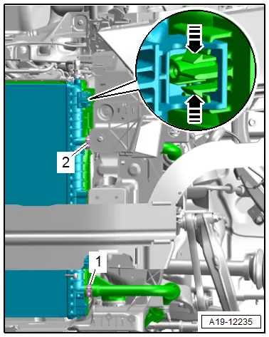
- Bring the radiator shutter as shown into the "half open" position.
- Remove the bolts -arrows-.
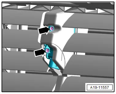
- Remove the connecting panel -2- with expanding pliers -1- from the slats.
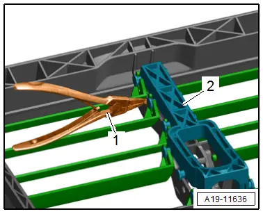
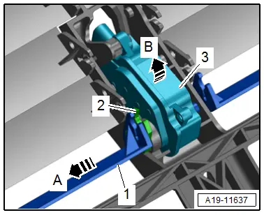
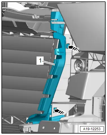
- Push the right upper slat -1- to the exterior in direction of -arrow A- and let it hang downward at the same time the driver -2- must remain in the adjustment motor -3-.
- Remove the driver from the adjustment motor.
- Pivot the adjustment motor in the direction of -arrow B- and remove from the mount.
Installing
Install in reverse order of removal and note the following:
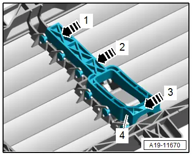
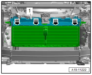
- To push on the connecting panel -4- bring all slats as shown into the "closed" position.
- Push in the connecting panel in direction of -arrows- at the same time pay attention to the sequence -1, 2 and 3-.
- Install the radiator shutter. Refer to → Chapter "Radiator Shutter, Removing and Installing".
Tightening Specifications
- Refer to → Chapter "Overview - Radiator/Radiator Fan"
Auxiliary Cooler, Removing and Installing
Charge Air Cooling Circuit Cooler, Removing and Installing
Special tools and workshop equipment required
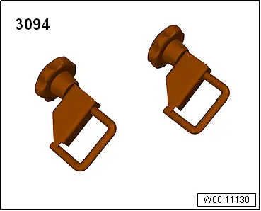
- Hose Clamps - Up To 25 mm -3094-
- Container of the Coolant Collection System -VAS5014- or the Shop Crane - Drip Tray -VAS6208-
- Hose Clip Pliers -VAS6362-
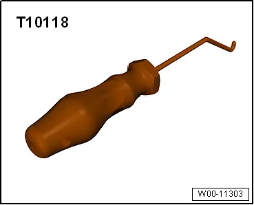
- Elbow Assembly Tool -T10118-
Removing
- Remove the front bumper cover. Refer to → Body Exterior; Rep. Gr.63; Front Bumper; Bumper Cover, Removing and Installing.
- Place the container of the Coolant Collection System -VAS5014- or the Shop Crane - Drip Tray -VAS6208- underneath.
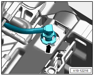
- Lift the clip -arrow- and remove the coolant line from the charge air cooling circuit cooler.
Versions without Radiator Shutter:
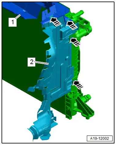
- Release the left and right catches with the Elbow Assembly Tool -T10118- in direction of -arrows- and remove the upper air ducts -1- and side air ducts -2-.
 Note
Note
For clarity, the installation position is shown with the radiator removed.
Versions with Radiator Shutter:
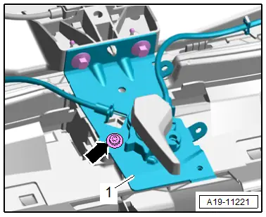
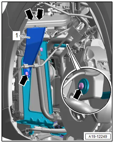
- Remove the bolts -arrows- and move the mounting bracket with release cable for the hook operating lever -1-.
- Release the catches in direction of -arrows- on the left and right sides and remove the air guide -1-.
- Open the catches in direction of -arrows- and remove the air duct -1-.
- Release the left and right catches using the Elbow Assembly Tool -T10118- in direction of -arrows- and remove the side air guide -1-.
 Note
Note
For clarity, the installation position is shown with the radiator removed.
Continuation for All Vehicles:
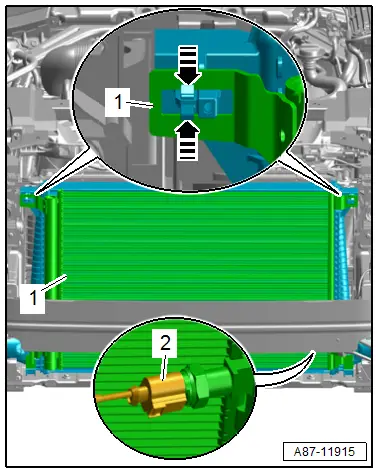
- Disconnect the connector -2- for the High Pressure Sensor -G65-.
 Caution
Risk of damaging the refrigerant lines and hoses.
Do not bend, twist or stretch the refrigerant lines and hoses.
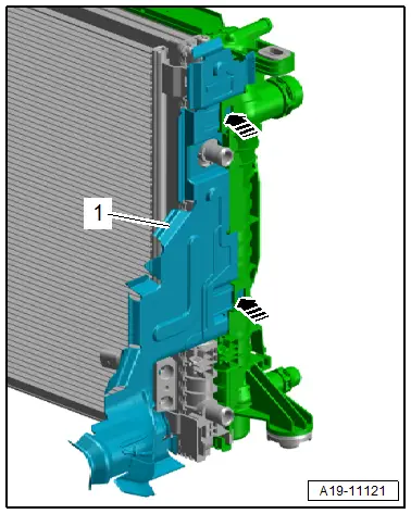
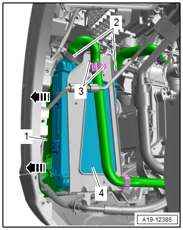
- Release the left and right catches in direction of -arrows- disengage the condenser from the radiator and tie up to the side.
- Loosen the hose clamps -1 and 2-, then clamp off the coolant hose from the charge air cooling circuit cooler with the Hose Clamps - Up To 25mm -3094- and remove the hose.
- Release the left and right catches -arrows- and remove the charge air cooling circuit cooler.
Installing
Install in reverse order of removal and note the following:
 Note
Note
- Secure all hose connections with hose clamps that match the ones used in series production. Refer to the Parts Catalog.
- All of the coolant must be changed if the radiator was replaced.
- Install the front bumper cover. Refer to → Body Exterior; Rep. Gr.63; Front Bumper; Bumper Cover, Removing and Installing.
- Connect the coolant hose to the connector coupling. Refer to → Fig. "Connect the Coolant Hose to the Connector Coupling".
 Note
Note
Used coolant cannot be used again.
- Fill with coolant.
Tightening Specifications
- Refer to → Chapter "Overview - Radiator/Radiator Fan"
- Refer to → Body Exterior; Rep. Gr.55; Hood; Overview - Release Cable.
Side Auxiliary Cooler, Removing and Installing
Special tools and workshop equipment required
- Hose Clamps - Up To 25 mm -3094-
- Hose Clip Pliers -VAS6362-
Removing
- Remove the front wheel. Refer to → Suspension, Wheels, Steering; Rep. Gr.44; Wheels and Tires.
- Remove the front section of the front wheel housing liner. Refer to → Body Exterior; Rep. Gr.66; Wheel Housing Liner; Front Wheel Housing Liner, Removing and Installing.
- Remove the bolts -arrows- and the bracket -1-.
 Note
Note
Place a cloth underneath to catch any escaping coolant.
- Loosen the hose clamps -2- to clamp off the coolant hoses with the Hose Clamps - Up To 25mm -3094- and remove them.
- Disengage the air guide -1- to the side in direction of -arrows- and leave in the installation position.
- Remove the bolts -3-, remove the auxiliary cooler -4- upward from the bracket and then remove it toward the rear.
Installing
Install in reverse order of removal and note the following:
 Note
Note
- Secure all hose connections with hose clamps that match the ones used in series production. Refer to the Parts Catalog.
- Used coolant cannot be used again.
- All of the coolant must be changed if the radiator was replaced.
- Fill with coolant.
Tightening Specifications
- Refer to → Chapter "Overview - Auxiliary Cooler"
- Refer to → Body Exterior; Rep. Gr.66; Wheel Housing Liner; Overview - Front Wheel Housing Liner.
- Refer to → Suspension, Wheels, Steering; Rep. Gr.44; Wheels and Tires.
Special Tools
Special tools and workshop equipment required
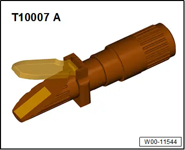
- Refractometer -T10007A-
- Elbow Assembly Tool -T10118-
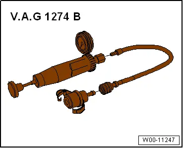
- Cooling System Tester -VAG1274B-
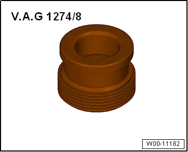
- Cooling System Tester - Adapter -VAG1274/8-
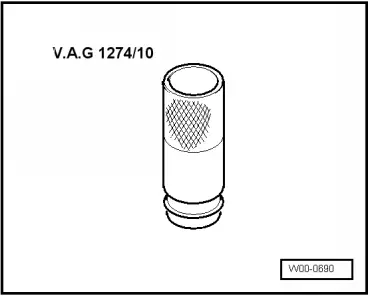
- Cooling System Tester - Adapter -VAG1274/10-
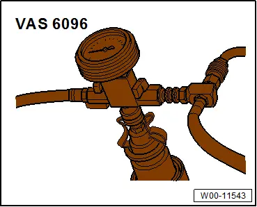
- Cooling System Charge Kit -VAS6096-
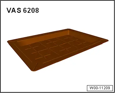
- Coolant Collection System -VAS5014- or Shop Crane - Drip Tray -VAS6208-
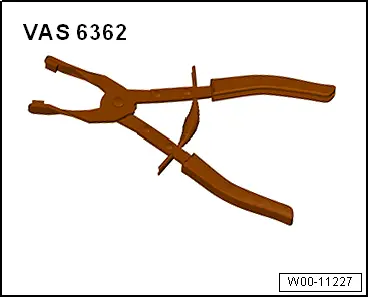
- Hose Clip Pliers -VAS6362-
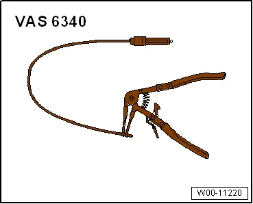
- Hose Clip Pliers -VAS6340-
- Hose Clamps - Up To 25mm -3094-
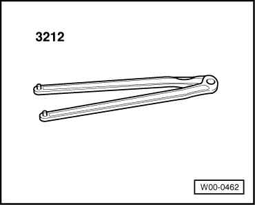
- Wrench - Pin Type -3212-
- Adapter VAG1274B/15 -VAG1274B/15-, not illustrated