Audi Q7: Flange Shaft Protective Ring, Replacing
Audi Q7 (4M) 2016-2026 Workshop Manual / Drivetrain / Rear Final Drive, Differential / Seals / Flange Shaft Protective Ring, Replacing
Flange Shaft Protective Ring, Replacing, 0DB and 0D2
Special tools and workshop equipment required
- Press Plate -VW401-
- Press Plate -VW402-
- Press Piece - Multiple Use -VW412-
- Press Piece - Deflection Ring -T40089/1-
- Intake Manifold Release Tool -T10526-
- -3-Separating Tool - 22-115mm, for example Puller - Kukko Quick Action Separating Tool - 22-115mm -17/2-
- Flange shaft removed.
Removing the Protective Ring -A- from the Flange Shaft
B - -17/2-, for example.
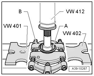
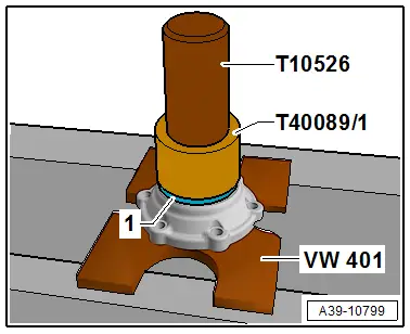
Installing the Protective Ring -1- on the Flange Shaft
- Installation position: the larger outer diameter of the protective ring faces toward the flange.
Flange/Driveshaft Protective Ring, Replacing
Flange/Driveshaft Protective Ring, Replacing, 0DB and 0D2
Special tools and workshop equipment required
- Press Plate -VW401-
- Press Piece - Rod -VW407-
- Press Piece - Multiple Use -VW412-
- Seal Installer - Flange Shaft -T10049-
- -3-Separating tool 22 to 75 mm, such as -17/1-
- Flange/driveshaft removed.
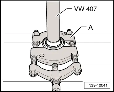
Press the Protective Ring off the Flange/Driveshaft.
A - Separating Tool - 22-115mm, such as -17/2-
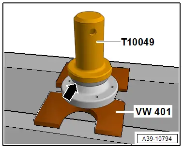
Install the Protective Ring -arrow- onto the Flange/Driveshaft.
- Installation position: ribbed side of the protective ring points to the flange.
- The protective ring -A- must engage audibly in the groove on the flange.