Audi Q7: Fuel Tank, Draining
Fuel Tank, Draining, Fuel Delivery Unit Not Faulty
Special tools and workshop equipment required
- Vehicle Diagnostic Tester
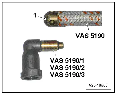
- Fuel Extraction Device -VAS5190A-
- Fuel Extraction - Adapter 2 -VAS5190/2-
Procedure
- Observe the safety precautions. Refer to → Chapter "Safety Precautions".
- Follow the guidelines for clean working conditions. Refer to → Chapter "Guidelines for Clean Working Conditions".
- Switch off the ignition.
- Attach a suitable adapter from the Fuel Extraction - Adapter Set -VAS5190/10- on the suction hose -1- from the Fuel Extractor -VAS5190A-.
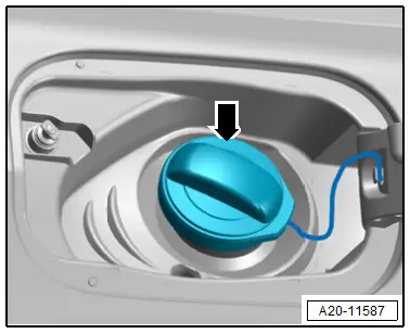
- Open the fuel filler door.

- Remove the fuel filler cap -arrow-.
 WARNING
Risk of explosion due to electrostatic charge.
Secure the Fuel Extraction Unit -VAS5190A- ground wire to a bare area of the body.
 WARNING
There is a risk of injury because the fuel is under high pressure.
To reduce the pressure in the fuel system, lay clean cloths around the connection point and carefully loosen the connection point.
- Free up the fuel hose from the brackets -1 and 3- and disconnect the connector coupling -2-. Refer to → Chapter "Connector Couplings, Disconnecting".
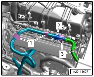
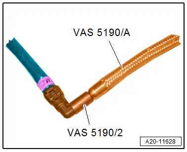
- Connect the suction hose with corresponding Fuel Extraction - Adapter 2 -VAS5190/2- on the supply line in the engine compartment.
- Use the Fuel Siphoning Device -VAS5190A- to drain the fuel tank through the supply line.
- Connect the Vehicle Diagnostic Tester.
- Switch the ignition on.
- Select and start OBD mode.
- Drivetrain
- Engine
- 01 - OBD-capable systems
- 01 - Engine electronics
- Basic setting
- Empty fuel tank
- Start the basic setting without measured values: the fuel pump starts.
- When no more fuel is extracted, press Stop.

Fuel Tank, Draining, Fuel Delivery Unit Faulty
Special tools and workshop equipment required
- Fuel Extraction Device -VAS5190A-
- Fuel Extraction - Adapter 2 -VAS5190/2-
Procedure
- Observe the safety precautions. Refer to → Chapter "Safety Precautions".
- Follow the guidelines for clean working conditions. Refer to → Chapter "Guidelines for Clean Working Conditions".
- Attach a suitable adapter from the Fuel Extraction - Adapter Set -VAS5190/10- on the suction hose -1- from the Fuel Extractor -VAS5190A-.
- Move the front seats all the way forward into the highest position.
- Switch off the ignition.
- Open the fuel filler door.
- Remove the fuel filler cap -arrow-.
 Caution
Risk of destroying electronic components when disconnecting the battery.
Follow the steps for disconnecting the battery.
- Disconnect the ground cable from the battery terminal. Refer to → Electrical Equipment; Rep. Gr.27; Battery; Battery, Disconnecting and Connecting.
 WARNING
Risk of explosion due to electrostatic charge.
Secure the Fuel Extraction Unit -VAS5190A- ground wire to a bare area of the body.
 WARNING
The fuel system is under pressure.
Risk of injury from fuel spraying out.
- Wear protective eyewear.
- Wear safety gloves.
- Reduce the pressure: place clean cloths around the connection point and carefully open the connection point.

- Free up the fuel hose from the brackets -1 and 3- and disconnect the connector coupling -2-. Refer to → Chapter "Connector Couplings, Disconnecting".

- Connect the suction hose with Fuel Extraction - Adapter 2 -VAS5190/2- on the supply line in the engine compartment.
 Caution
Danger of fuel entering vehicle interior.
Also in only partly filled fuel tanks, the fuel in the right container half can be up the height of the sealing flange. For this reason approximately 15 liters (3.96 gallons) of fuel must be extracted using the Fuel Extractor -VAS5190A- before opening the sealing flange.
- Extract approximately 15 liters (3.96 gallons) of fuel with the Fuel Extractor -VAS5190A- through the supply line.
- Remove the right rear and front sill panel. Refer to → Body Interior; Rep. Gr.70; Vehicle Interior Trim Panels; Sill Panel, Removing and Installing.
- Remove the bench seat / right and center single seats. Refer to → Body Interior; Rep. Gr.72; Rear Seats; Bench Seat/Single Seat, Removing and Installing.
- Remove the support for the right luggage compartment floor. Refer to → Body Interior; Rep. Gr.70; Luggage Compartment Trim Panels; Overview - Luggage Compartment Floor.
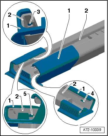
- Remove the cover -1- on the front passenger seat behind both seat rails, to do so release the tabs -3, 4 and 5- carefully on the seat rail -2-.
 Note
Note
The front passenger seat does not need to be removed.
- Remove the carpet under the seat rail.
- Remove the cover and connector station for the bench seat / single seat in the carpet.
- Fold the carpet near the sealing flange cover to the side.
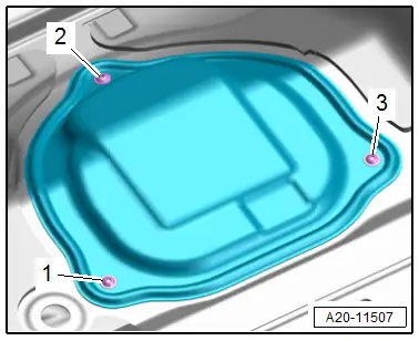
- Remove the bolts -1, 2 and 3- and remove the sealing flange cover.
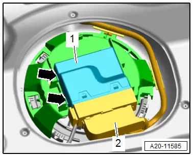
- Release the catches -arrows- using a screwdriver and remove the Fuel Pump Control Module -J538--1- from the bracket.
- Release the connector safety catch and disconnect the connector -2- for the Fuel Pump Control Module -J538-.
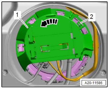
- Release the catch -2- with a screwdriver and turn the bracket -1- for the Fuel Pump Control Module -J538- counter-clockwise in the direction of -arrow-.
- Disengage the bracket on the locking ring and remove.
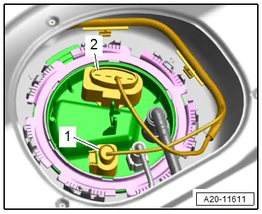
- Disconnect the connectors -1 and 2- on the sealing flange by releasing the connector safety catch.
- Remove the fuel line -2- from the sealing flange. Disconnect the connector couplings. Refer to → Chapter "Connector Couplings, Disconnecting".
 WARNING
Danger due to escaping fuel.
To prevent large quantities of fuel from leaking from the fuel delivery unit when removing, the fuel tank may only be a maximum of 1/4 full.
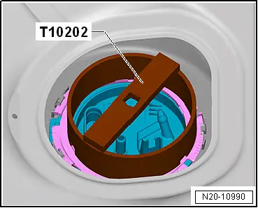
- Remove the locking ring using the Wrench - Fuel Sending Unit -T10202-.
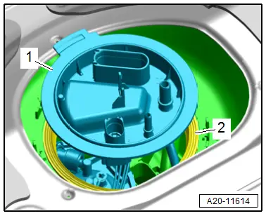
- Pull the sealing flange -1- just slightly out of the opening in the fuel tank and remove the gasket -2-.
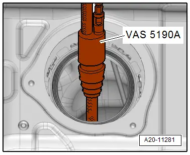
- With the sealing flange raised push the suction hose from the Fuel Extractor -VAS5190A- through the opening in the fuel tank.
- Extract fuel from both fuel tank chambers with the Fuel Extractor -VAS5190A-.
Assembling
Assemble in the reverse order of removal. Note the following:
- Install the support for the luggage compartment floor. Refer to → Body Interior; Rep. Gr.70; Luggage Compartment Trim Panels; Overview - Luggage Compartment Floor.
- Install the bench seat / single seat. Refer to → Body Interior; Rep. Gr.72; Rear Seats; Bench Seat/Single Seat, Removing and Installing.
- Install the sill panel. Refer to → Body Interior; Rep. Gr.70; Vehicle Interior Trim Panels; Overview - Sill Panel Strip.

