Audi Q7: Fuel Tank, Removing and Installing
Special tools and workshop equipment required
- Engine and Gearbox Jack -VAS6931-
- Gearbox Support -T40173-
Removing
- Follow all safety precautions. Refer to → Chapter "Safety Precautions".
- Follow the guidelines for clean working conditions. Refer to → Chapter "Guidelines for Clean Working Conditions".
 Caution
Risk of destroying electronic components when disconnecting the battery.
Follow the steps for disconnecting the battery.
- Disconnect the ground cable from the battery terminal. Refer to → Electrical Equipment; Rep. Gr.27; Battery; Battery, Disconnecting and Connecting.
 WARNING
Risk of accident due to the weight of the fuel tank.
The fuel tank must be empty when removing it.
- Drain the fuel tank. Refer to → Chapter "Fuel Tank, Draining".
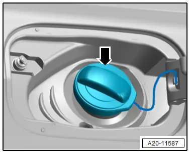
- Open the fuel filler door.
- Clean the area around the fuel filler neck.
- Remove the fuel filler cap -arrow-.
 Note
Note
Seal the fuel filler neck opening with a clean plug to prevent any dirt from getting in.
- Remove the right rear wheel housing liner. Refer to → Body Exterior; Rep. Gr.66; Wheel Housing Liner; Rear Wheel Housing Liner, Removing and Installing.
- Remove the fuel filler door unit. Refer to → Body Exterior; Rep. Gr.55; Fuel Filler Door Unit; Fuel Filler Door Unit, Removing and Installing.
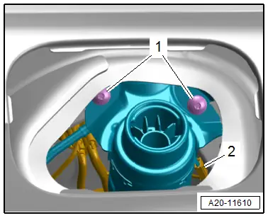
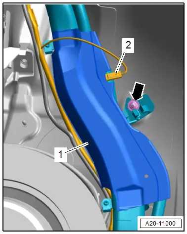
- Remove the fuel filler neck bolts -1-.
- Disconnect the ground -2- from the fuel filler neck metal ring.
- Remove the nut -arrow- for the fuel filler neck.
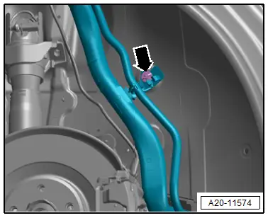
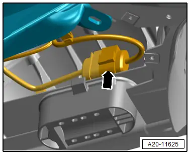
- Disconnect the bleeder line -1- from the EVAP canister. Disconnect the connector couplings. Refer to → Chapter "Connector Couplings, Disconnecting".
- Disengage and free up the bleeder line at the bracket -arrow-.
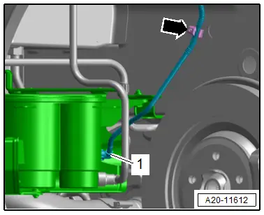
- Disconnect the ground wire -2- from the fuel filler neck protective plate -1-.
- Remove the nut -arrow- for the fuel filler neck.
- Disconnect the bleeder line -1- from the EVAP canister. Disconnect the connector couplings. Refer to → Chapter "Connector Couplings, Disconnecting".
- Remove the fuel tank pressure sensor with the bracket. Refer to → Chapter "Fuel Tank Pressure Sensor -G400-, Removing and Installing".
- Disengage and free up the bleeder line at the bracket -arrow-.
- Remove the rear underbody trim panels. Refer to → Body Exterior; Rep. Gr.66; Underbody Trim Panel; Underbody Trim Panels, Removing and Installing.
- Remove the diagonal braces. Refer to → Body Exterior; Rep. Gr.66; Underbody Trim Panel; diagonal braces, removing and installing.
- Remove the rear section of the exhaust system. Refer to → Rep. Gr.26; Exhaust Pipes/Mufflers; Muffler, Removing and Installing.
- Remove the driveshaft. Refer to → Rep. Gr.39; Driveshaft; Driveshaft, Removing and Installing.
- Remove the subframe. Refer to → Suspension, Wheels, Steering; Rep. Gr.42; Subframe; Overview - Subframe.
 WARNING
The fuel system is under pressure.
Risk of injury from fuel spraying out.
- Wear protective eyewear.
- Wear safety gloves.
- Reduce the pressure: place clean cloths around the connection point and carefully open the connection point.
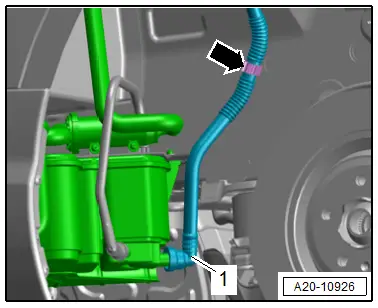
- Disconnect the fuel line -2-. Disconnect the connector couplings. Refer to → Chapter "Connector Couplings, Disconnecting".
 Note
Note
Ignore item -1-.
- Disconnect the connector -arrow- for the fuel delivery unit.
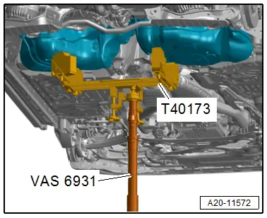
- Attach the Gearbox Support -T40173- on the Engine and Gearbox Jack -VAS6931- and position it to support the fuel tank, as shown.
 WARNING
Risk of accident due to the weight of the fuel tank.
The fuel tank must be empty when removing it.
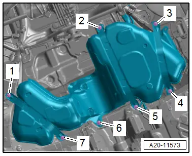
- Remove the bolts -1 through 7-.
 Note
Note
For clarity, the fuel tank is shown without the engine and gearbox jack.
- Lower the fuel tank with the Engine and Gearbox Jack -VAS6931-.
- By turning it accordingly, lower the fuel tank sideways and remove it.
 Note
Note
When guiding out the fuel tank check the clearance to the fuel filler neck.
Installing
Install in reverse order of removal and note the following:
- The fuel lines as well as the wiring harness to the fuel delivery unit must be clipped in the fuel tank.
- The connectors on the sealing flange must be connected and engaged securely.
- The ground wire connector must not show signs of oxidation, if necessary remove the oxidation.
- Position the fuel tank with mounting straps on the underbody using the Engine and Gearbox Jack -VAS6931-.

- When positioning the fuel tank, make sure that the fuel filler neck is guided into the opening of the body correctly.
- Disconnect the ground wire -2- on the fuel filler neck metal ring.
- Make sure that the connectors are securely fastened.
- Tighten the bolts -1- on the fuel filler neck.

 WARNING
Danger due to electrostatic charge.
After installing, check electrical connection on fuel filler neck threaded ring to an empty spot on the body using an Ohm meter.
Specified value: approximately 0 Ω.
- Tighten the bolts -1 through 7- on the mounting strap and the fuel tank.
- Install the subframe. Refer to → Suspension, Wheels, Steering; Rep. Gr.42; Subframe; Overview - Subframe.
- Install the driveshaft. Refer to → Rep. Gr.39; Driveshaft; Driveshaft, Removing and Installing.
- Install the fuel filler door unit. Refer to → Body Exterior; Rep. Gr.55; Fuel Filler Door Unit; Fuel Filler Door Unit, Removing and Installing.
- Connect the battery. At the same time, follow all steps after connecting the battery. Refer to → Electrical Equipment; Rep. Gr.27; Battery; Battery, Disconnecting and Connecting.
- After installing a new or completely empty fuel tank, at least 5 liters (1.32 gallons) of fuel must be added before starting the engine.

 Note
Note
Do not allow the fuel pump to run when the fuel tank is empty.
Tightening Specifications
- Refer to → Chapter "Overview - Fuel Tank".
- Refer to → Body Exterior; Rep. Gr.66; Underbody Trim Panel; Overview - Underbody Trim Panels.
- Refer to → Body Exterior; Rep. Gr.55; Fuel Filler Door Unit; Overview - Fuel Filler Door Unit.
- Refer to → Rep. Gr.26; Exhaust Pipes/Mufflers; Overview - Muffler.
- Refer to → Body Exterior; Rep. Gr.66; Underbody Trim Panel; Overview - Diagonal Braces.
- Refer to → Body Exterior; Rep. Gr.66; Wheel Housing Liner; Overview - Rear Wheel Housing Liner.
- Refer to → Suspension, Wheels, Steering; Rep. Gr.44; Wheels and Tires.

