Audi Q7: Connector Couplings
Connector Couplings, Disconnecting
Connector Coupling Allocation
 Note
Note
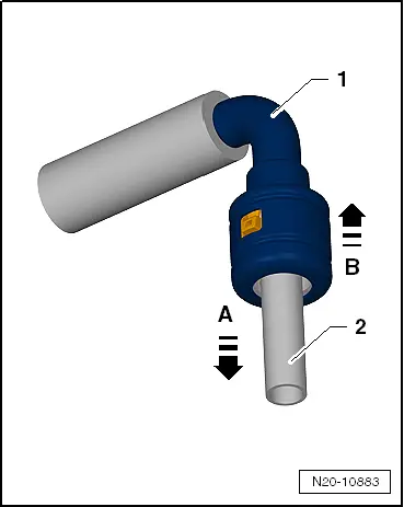
The connector couplings for fuel, vacuum and breather lines are color-coded. There is either a colored dot on the connector coupling, or the release button has the corresponding color.
Color Coding
 WARNING
The fuel system is under pressure.
Risk of injury from fuel spraying out.
- Wear protective eyewear.
- Wear safety gloves.
- Reduce the pressure: place clean cloths around the connection point and carefully open the connection point.
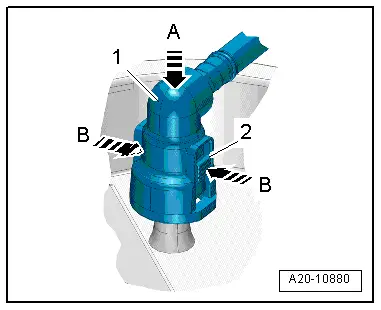
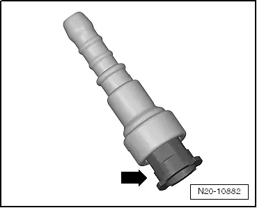
Version 1
Connector coupling with right and left release buttons -arrows-.
Opening
- Push the connector coupling -1- in the direction of -arrow A-.
- Push the release buttons and hold them pressed.
- Disconnect the connector coupling -1- from the fuel line -2- in the direction of -arrow B-.
- Pay attention to the color coding during installation.
- The connector couplings must "audibly" engage when locking.
- Pull on the connector coupling to check for secure fit.
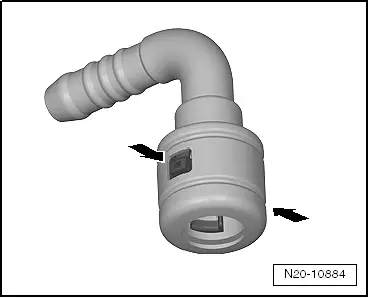
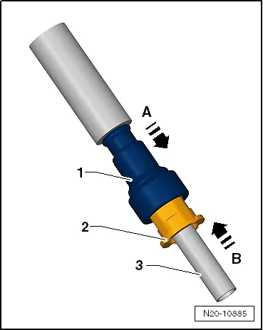
Version 2
Connector coupling with pull release -arrow-:
Opening
- Push the connector coupling -1- in the direction of -arrow A-.
- Pull the pull release -2- in the direction of -arrow B-.
- Pull the connector coupling -1- off the fuel line -3- in the direction of -arrow B-.
- Pay attention to the color coding during installation.
- The connector couplings must "audibly" engage when locking.
- Pull on the connector coupling to check for secure fit.
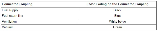
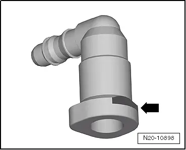
Version 3
Connector coupling with front button -arrow-:
Opening
- Press the release button -arrow- and remove the connector couplings.
- Pay attention to the color coding during installation.
- The connector couplings must "audibly" engage when locking.
- Pull on the connector coupling to check for secure fit.
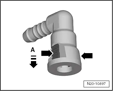
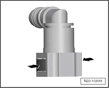
Version 4
Connector coupling with right and left release button -arrows-:
Opening
- Push the connector coupling in the direction of -arrow A-.
- Press the release buttons -arrows- and remove the connector coupling.
- Pay attention to the color coding during installation.
- The connector couplings must "audibly" engage when locking.
- Pull on the connector coupling to check for secure fit.
Version 5
Connector coupling with right and left release buttons -arrows-:
Opening
- Press the release buttons -arrows- and remove the connector coupling.
- Pay attention to the color coding during installation.
- The connector couplings must "audibly" engage when locking.
- Pull on the connector coupling to check for secure fit.
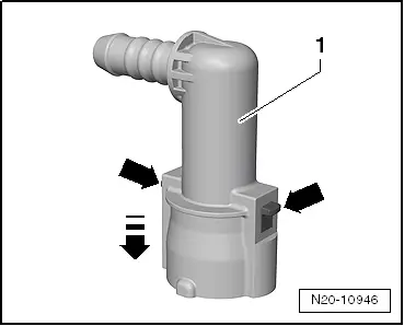
Version 6
Connector coupling with right and left release buttons -arrows-:
Opening
- Press the connector coupling -1- in the direction of -arrow- and hold it down.
- Press the release buttons -arrows- and remove the connector coupling.
- Pay attention to the color coding during installation.
- The connector couplings must "audibly" engage when locking.
- Pull on the connector coupling to check for secure fit.
Version 7
Connector coupling -1- with right and left release buttons -2-:
Opening
- Press the connector coupling -1- in the direction of -arrow A- and hold it down.
- Push the release buttons -2- in the direction of -arrow B- and remove the connector coupling -1-.
- Pay attention to the color coding during installation.
- The connector couplings must "audibly" engage when locking.
- Pull on the connector coupling to check for secure fit.