Audi Q7: High Pressure Sensor -G65-, Checking, Removing and Installing
High Pressure Sensor -G65-, Removing and Installing
 WARNING
Danger due to refrigerant coming out under pressure when there is a faulty valve in the refrigerant circuit.
Danger of frost bite to skin and other parts of the body.
- If the refrigerant starts to leak out of the refrigerant line longer than 1 second when loosening the High Pressure Sensor -G65-, retighten the High Pressure Sensor -G65- immediately.
- Extract the refrigerant to remove and Install. Refer to → Refrigerant R134a Servicing; Rep. Gr.87; Refrigerant Circuit.
- Replace the defective valve in the refrigerant line. Refer to → Refrigerant R134a Servicing; Rep. Gr.87; A/C System, General Information.
 Note
Note
- The coolant performance cannot be checked when the High Pressure Sensor -G65- is removed, the Front A/C Display Control Head -E87-, does not activate the A/C compressor. Refer to Vehicle Diagnostic Tester in the "Guided Fault Finding" function.
- The refrigerant circuit remains closed, connection with valve.
- On this vehicle only the High Pressure Sensor -G56- may be installed otherwise information is exchanged via the local data bus with the Front A/C Display Control Head -E87-. Refer to the Parts Catalog.
- On these vehicles no High Pressure Sensor -G65- can be installed, otherwise square-wave signal are admitted (which could have the same construction, only vary by the part number). Refer to the Parts Catalog.
Removing
- Turn off the ignition.
- Remove the cover on the lock carrier and the left air intake motor. Refer to → Body Exterior; Rep. Gr.63; Front Bumper; Attachments, Removing and Installing.
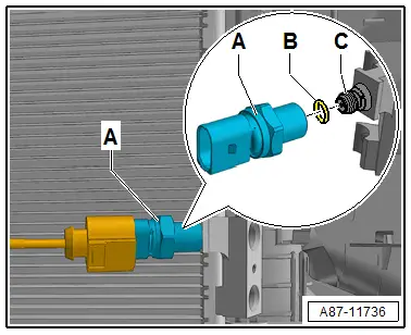
- Disconnect the connector -A-.

- Remove the High Pressure Sensor -G65--A- from the connection on the condenser -C-.
Installing
Installation is done is reverse order, observe the following:
- Replace the O-ring -B-, before installing coat lightly with refrigerant oil. Refer to → Chapter "Refrigerant Circuit Seals" and to the Parts Catalog for the allocation.
- Tighten the High Pressure Sensor -G65--A-.
- Tightening Specification: 5 Nm
- Check the DTC memory on the Front A/C Display Control Head -E87- and erase any displayed malfunctions. Refer to Vehicle Diagnostic Tester in the "Guided Fault Finding" function.
High Pressure Sensor -G65-, Checking
Procedure
Check the signal from the High Pressure Sensor -G65--B-. Refer to Vehicle Diagnostic Tester in the "Guided Fault Finding" function.
 Note
Note
- The signal from the High Pressure Sensor -G65- is checked as described in the Guided Fault Finding of the A/C system. Refer to Vehicle Diagnostic Tester in the "Guided Fault Finding" function.
- The signal from the High Pressure Sensor -G65- is transferred via a local data bus to the Front A/C Display Control Head -E87-. Refer to Vehicle Diagnostic Tester in the "Guided Fault Finding" function and refer to → Wiring diagrams, Troubleshooting & Component locations.
- If an error signal is detected from the High Pressure Sensor -G65-, the error is entered in the Front A/C Display Control Head -E87- DTC memory. When reading out the DTC memory of the Front A/C Display Control Head -E87-, check the DTC memory of the Front A/C Display Control Head -E87-. Refer to Vehicle Diagnostic Tester in the "Guided Fault Finding" function.
- The measured values of the High Pressure Sensor -G65- is displayed in the "read measured values" function of the Guided Fault Finding of the Front A/C Display Control Head -E87-. Refer to Vehicle Diagnostic Tester in the "Guided Fault Finding" function.

High Pressure Sensor -G65-, Checking Pressure Signal
 Note
Note
- The coolant performance cannot be checked with the connector -A- removed or when the High Pressure Sensor -G65--B- is removed, the Front A/C Display Control Head -E87-, does not activate the A/C compressor. Refer to Vehicle Diagnostic Tester in the "Guided Fault Finding" function.
- To check the measured value of the High Pressure Sensor -G65-. Refer to Vehicle Diagnostic Tester in the function "Guided Fault Finding".
- The High Pressure Sensor -G65- exchanges information with the Front A/C Display Control Head -E87- via the local data bus.
- On this vehicle only the High Pressure Sensor -G56- may be installed otherwise information is exchanged via the local data bus with the Front A/C Display Control Head -E87-. Refer to the Parts Catalog.
- On these vehicles no High Pressure Sensor -G65- can be installed, otherwise square-wave signal are admitted (which could have the same construction, only vary by the part number). Refer to the Parts Catalog.
- On this vehicle, it may take a while until the pressure on the high pressure side comes down after the A/C compressor is switched off. The expansion valve(s) is/are "cold" and the pressure on the low pressure side increases quickly after deactivation, the expansion valve(s) closes/close and the refrigerant can flow only slowly on the low pressure side.
Preparation
- Turn off the ignition.
- Remove the cover on the lock carrier and the left air intake motor. Refer to → Body Exterior; Rep. Gr.63; Front Bumper; Attachments, Removing and Installing.

- Disconnect the connector -A-.
3-Way Connector Assignment High Pressure Sensor -G65--A- → Wiring diagrams, Troubleshooting & Component locations
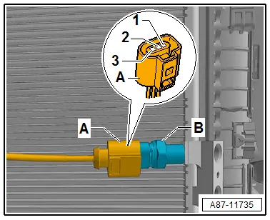
1 - Ground
2 - Signal output - via the local data bus to the Front A/C Display Control Head -E87-
3 - Terminal "75" (positive)
Test Sequence
- Turn on the ignition.
- Check the ground and positive connection to the terminal -A- .
- Check the connection and the function of the High Pressure Sensor -G65- as described in the Guided Fault Finding. Refer to Vehicle Diagnostic Tester in the "Guided Fault Finding" function.
 Note
Note
- The A/C compressor (A/C Compressor Regulator Valve -N280-) is not actuated when the connector -A- is disconnected.
- The High Pressure Sensor -G65- is an electronic control module that exchanges information with the Front A/C Display Control Head -E87- via a local data bus. Refer to Vehicle Diagnostic Tester in the "Guided Fault Finding" function.

