Audi Q7: Air Intake and Outlet Openings
Air Intake and Outlet Openings in Front Heater and A/C Unit
The passenger compartment is ventilated via two ventilation frames (in the luggage compartment on the right and left near the bumper). Refer to → Chapter "Vehicle Interior Forced Air Extraction, Removing and Installing".
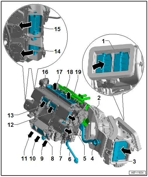
1 - Fresh Air Intake
- The air is extracted out of the plenum chamber. Refer to → Chapter "Fresh Air Intake, Removing and Installing".
2 - Air Intake Housing
- Refer to → Chapter "Overview - Heater and A/C Unit Air Intake Housing"
3 - Air Intake from the Vehicle Interior (in Recirculating Air Mode)
- The air is taken from the passenger footwell under the glove compartment.
4 - Air Duct for Glove Compartment Cooling
- Refer to → Chapter "Air Guide for Glove Compartment Cooling, Removing and Installing"
 Note
Note
- Only on vehicles with the "glove compartment cooling" optional equipment installed. Refer to → Chapter "Air Guide for Glove Compartment Cooling, Removing and Installing".
- On vehicles without the "glove compartment cooling" optional equipment the connection is closed with a cap.
5 - Air Vent to the Vent in the Instrument Panel on the Right Side (and to the Broadband Nozzle)
- Depending on the version of the A/C system the air is guided to different vents. Refer to → Chapter "Overview - Air Routing and Air Distribution in Passenger Compartment, Front".
6 - Right Condensation Water Drain
- Refer to → Chapter "Condensation Water Drain, Removing and Installing"
7 - Air Vent to Right Front Footwell Vent
8 - Left Condensation Water Drain
- Refer to → Chapter "Condensation Water Drain, Removing and Installing"
9 - Air Vent to the Air Ducts under the Right Center Console
- Depending on the setting, different temperatures for the left and right side are possible. Refer to → Chapter "Air Duct in Front Heater and A/C unit ".
 Note
Note
Depending on the version of the A/C system only an air duct, a rear air distribution housing or a rear heater and A/C unit is installed. Refer to → Chapter "Air Ducts and Vents in the Rear Vehicle Interior, High A/C System".
10 - Air Vent to the Air Ducts under the Center Console
- Depending on the adjustment different temperatures of the air for the left and right side are possible, a temperature is set in the center, which is determined from the temperature set at the left and right and the adjusted air quantity. Refer to → Chapter "Air Duct in Front Heater and A/C unit ".
 Note
Note
Depending on the version of the A/C system only an air duct, a rear air distribution housing or a rear heater and A/C unit is installed. Refer to → Chapter "Air Ducts and Vents in the Rear Vehicle Interior, High A/C System".
11 - Air Vent to the Air Ducts under the Left Center Console
- Depending on the setting, different temperatures for the left and right side are possible. Refer to → Chapter "Air Duct in Front Heater and A/C unit ".
 Note
Note
Depending on the version of the A/C system only an air duct, a rear air distribution housing or a rear heater and A/C unit is installed. Refer to → Chapter "Air Ducts and Vents in the Rear Vehicle Interior, High A/C System".
12 - Air Vent to the Center Vent of the Right Instrument Panel
- Depending on the setting, different temperatures for the left and right side are possible. Refer to → Chapter "Air Duct in Front Heater and A/C unit ".
13 - Air Vent to the Center Vent of the Left Instrument Panel
- Depending on the setting, different temperatures for the left and right side are possible. Refer to → Chapter "Air Duct in Front Heater and A/C unit ".
14 - Air Vent to the Front Left Footwell Vent
- Depending on the setting, different temperatures for the left and right side are possible. Refer to → Chapter "Air Duct in Front Heater and A/C unit ".
15 - Air Outlet to the Vents on the Left Side of the Instrument Panel
- Depending on the setting, different temperatures for the left and right side are possible. Refer to → Chapter "Air Duct in Front Heater and A/C unit ".
16 - Front Heater and A/C Unit Air Distribution Housing
- There are different versions. Refer to the Parts Catalog.
- Refer to → Chapter "Overview - Heater and A/C Unit"
- Refer to → Chapter "Heater and A/C Unit, Removing and Installing"
17 - Air Vent to the Left Instrument Panel Defroster Vent
- Depending on the setting, different temperatures for the left and right side are possible. Refer to → Chapter "Air Duct in Front Heater and A/C unit ".
18 - Air Vent to the Right Instrument Panel Defroster Vent
- Depending on the setting, different temperatures for the left and right side are possible. Refer to → Chapter "Air Duct in Front Heater and A/C unit ".
19 - Evaporator Housing
- Refer to → Chapter "Overview - Evaporator Housing"
- Refer to → Chapter "Heater and A/C Unit, Removing and Installing"
Air Duct in Front Heater and A/C unit
 Note
Note
- Depending on vehicle equipment, there are different versions of the A/C system for the Audi Q7. Make sure to use the correct version and pay attention to the allocation of different components. Refer to → Chapter "A/C System Versions" and Parts Catalog.
- In order to show the air routing in the air intake housing and in the Heater and A/C unit, both of these components are shown cut along lines "A - A" and "B - B" and "C- C".
- On vehicles with glove compartment cooling, the cooled air comes directly past the evaporator into the glove compartment -item 11-.
- For the temperature of the air from the front vents to be regulated separately, separator walls are installed in the front Heater and A/C unit (not shown in detail here).
- The passenger compartment is ventilated via two ventilation frames (in the luggage compartment on the right and left near the bumper). Refer to → Chapter "Vehicle Interior Forced Air Extraction, Removing and Installing".
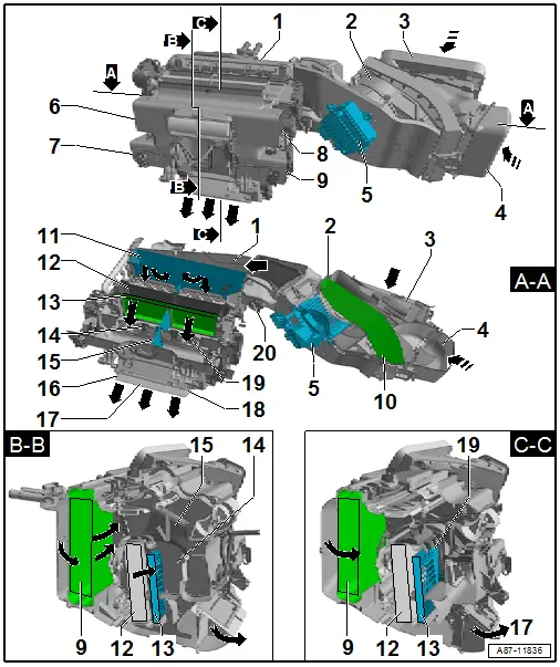
1 - Front Heater and A/C Unit Evaporator and Air Distribution Housing
- There are different versions. Refer to the Parts Catalog.
- Refer to → Chapter "Overview - Heater and A/C Unit"
2 - Front Heater and A/C Unit Air Intake Housing
3 - Fresh Air Intake
- The air is extracted out of the plenum chamber. Refer to → Chapter "Fresh Air Intake, Removing and Installing".
4 - Air Intake from the Vehicle Interior (in Recirculating Air Mode)
- The air is drawn out of the front passenger footwell when the air recirculation flap under the glove compartment is open.
- In this illustration, the air recirculation door is shown in the "closed" position.
5 - Fresh Air Blower -V2- with Fresh Air Blower Control Module -J126-
6 - Air Vent to the Left Instrument Panel Vent (Driver Side)
7 - Air Vent to the Left Footwell Vent (Driver Side)
8 - Air Vent to the Right Instrument Panel Vent (Front Passenger Side)
- On vehicles with a "Mix" or "High" A/C system also to the broadband nozzle
9 - Air Vent to the Right Footwell Vent (Front Passenger Side)
10 - Dust and Pollen Filter
- There are different versions. Refer to the Parts Catalog.
- Refer to → Chapter "Dust and Pollen Filter with Activated Charcoal Insert, Element Information"
11 - Evaporator
12 - Heater Core for the Heater
- Refer to → Chapter "Heater Core, Removing and Installing"
13 - Zone Partition Grille or Auxiliary Heater Heating Element -Z35- (with the Auxiliary Heater Control Module -J604-)
- The Auxiliary Heater Heating Element -Z35- (with the Auxiliary Heater Control Module -J604-) is currently installed in vehicles with a diesel engine. Refer to → Chapter "Electrical Auxiliary Heater, Testing".
- On vehicles with a gasoline engine currently no Auxiliary Heater Heating Element -Z35- is installed here a zone partition grille is used
- If a parking heater installed as optional equipment is activated as an auxiliary heater in vehicles with a diesel engine, no Auxiliary Heater Heating Element -Z35- is installed (implementation not yet finalized). Refer to → Chapter "Electrical Auxiliary Heater, Testing". On this vehicle a zone partition grille is present
14 - Front Left Mixing Chamber for Warmed and not Warmed Air (Driver Side)
- Via the various temperature control doors a certain part of the air is directed through or past the heat exchanger (and the Auxiliary Heater Heating Element -Z35- or the zone partition grille)
- The temperature control doors for the front are not shown here
15 - Separator between the Driver and Front Passenger Side
- Separates the air duct to the left and right vents and is responsible for the differing temperatures of the air coming out of the vents. Depending on the position of the particular air door.
16 - Left Rear Air Vent (Driver Side)
- Depending on the adjustment the warmed or cooled air can be directed to the vents
- The rear temperature control door is not shown here
- On a heater and A/C unit for a "Low" or "Mid" A/C system the door for the air vent in the rear (-16-, -17- and -18- ) are joined with each other via a curved washer depending on the position as closed or open (only the door -16- and -18-) via the shaft.
- On a heater and A/C unit for a "Mix" or "High" A/C system the doors for the air vent in the front area -16-, -17- and -18- are closed or opened at the same time (they are attached with each other via the shaft).
 Note
Note
- For vehicles with a "Low" A/C system the air is directed over the air ducts in the left rear footwell. Refer to → Chapter "Rear Air Duct, Low A/C System".
- On vehicles with a "Mid" or "Mix" A/C system the air is directed via the air ducts to the rear air distribution housing and there is it mixed with the air from the center front area air vent. Refer to → Chapter "Air Duct in Rear Air Distribution Housing, Mid or Mix A/C System".
- On vehicles with a "High" A/C system the air is directed over the air ducts to the rear heater and A/C unit, and there is mixes with the air from the center front area air vent and is cooled or warmed. Refer to → Chapter "Air Duct in the Rear Heater and A/C Unit, High A/C System".
17 - Cent Front Area Air Vent
- Depending on the adjustment the warmed or cooled air can be directed to the vents
- The rear temperature control door is not shown here
- On a heater and A/C unit for a "Low" or "Mid" A/C system the doors for the air vent in the front area (-item 16-, -17- and -18-) is closed or opened via a curved washer depending on the position (only the door -item 16- and - are attached with each other via the shaft).
- On a heater and A/C unit for a "Mix" or "High" A/C system the doors for the air vent in the front area -16-, -17- and -18- are closed or opened at the same time (they are attached with each other via the shaft).
 Note
Note
- For vehicles with a "Low" A/C system the air is directed over the air ducts to the center console vent. Refer to → Chapter "Rear Air Duct, Low A/C System".
- On vehicles with a "Mid" or "Mix" A/C system the air is directed via the air ducts to the rear air distribution housing and there is it mixed with the air from the left and right footwell air vent. Refer to → Chapter "Air Duct in Rear Air Distribution Housing, Mid or Mix A/C System".
- On vehicles with a "High" A/C system the air is directed over the air ducts to the rear heater and A/C unit, and there is mixes with the air from the left and right footwell air vent and is cooled or warmed. Refer to → Chapter "Air Duct in the Rear Heater and A/C Unit, High A/C System".
18 - Right Front Area Air Vent (Front Passenger Side)
- Depending on the adjustment the warmed or cooled air can be directed to the vents
- The rear temperature control door is not shown here
- On a heater and A/C unit for a "Low" or "Mid" A/C system the doors for the air vent in the front area (-item 16-, -item 17- and -item 18-) is closed or opened via a curved washer depending on the position (only the door -item 16- and -item 18- are attached with each other via the shaft).
- On a heater and A/C unit for a "Mix" or "High" A/C system the doors for the air vent in the front area -16-, -17- and -18- are closed or opened at the same time (they are attached with each other via the shaft).
 Note
Note
- For vehicles with a "Low" A/C system the air is directed over the air ducts in the left rear footwell. Refer to → Chapter "Rear Air Duct, Low A/C System".
- On vehicles with a "Mid" or "Mix" A/C system the air is directed via the air ducts to the rear air distribution housing and there is it mixed with the air from the center front area air vent. Refer to → Chapter "Air Duct in Rear Air Distribution Housing, Mid or Mix A/C System".
- On vehicles with a "High" A/C system the air is directed over the air ducts to the rear heater and A/C unit, and there is mixes with the air from the center front area air vent and is cooled or warmed. Refer to → Chapter "Air Duct in the Rear Heater and A/C Unit, High A/C System".
19 - Front Right Mixing Chamber for Warmed and not Warmed Air (Front Passenger Side)
- Via the various temperature control doors a certain part of the air is directed through or past the heat exchanger (and the Auxiliary Heater Heating Element -Z35- or the zone partition grille)
- The temperature control doors for the front are not shown here
20 - Connection for the Hose to the Air Duct for Glove Compartment Cooling
- On vehicles without the optional equipment of "glove compartment cooling", the opening in the heater and A/C unit is sealed with a cap. Refer to → Chapter "Air Guide for Glove Compartment Cooling, Removing and Installing"
- Glove compartment cooling air duct hose, checking, Removing and installing. Refer to → Chapter "Air Guide for Glove Compartment Cooling, Removing and Installing".
Rear Air Duct, "Low" A/C System
 Note
Note
- Depending on vehicle equipment, there are different versions of the A/C system for the Audi Q7. Make sure to use the correct version and pay attention to the allocation of different components. Refer to → Chapter "A/C System Versions" and Parts Catalog.
- On vehicles with a "Low" A/C system no activation or regulation of the rear air distribution takes place via the components, which are installed under the center console. On these vehicles the air distribution take place for the front area exclusively via the heater and A/C unit. Refer to → Chapter "Air Ducts and Vents in the Rear Vehicle Interior, Low A/C System".
Air Duct in Rear Air Distribution Housing, "Mid" or "Mix" A/C System
 Note
Note
- Depending on vehicle equipment, there are different versions of the A/C system for the Audi Q7. Make sure to use the correct version and pay attention to the allocation of different components. Refer to → Chapter "A/C System Versions" and Parts Catalog.
- The rear air distribution housing and the Rear A/C Display Control Head -E265- are optional equipment (only installed on a "Mid" or "Mix" A/C system).
- The temperature from the rear vent is regulated from the Front A/C Display Control Head -E87- via the setting for the front vent, the measured value of the Rear Upper Body Vent Temperature Sensor -G537- and the setting on the Position Sensor in Left Rear Upper Body Vent -G630-, on the Position Sensor in Right Rear Upper Body Vent - G631- and on the Rear A/C Display Control Head -E265-. Refer to Vehicle Diagnostic Tester in the "Guided Fault Finding" function.
- No doors are installed inside the rear air distribution housing. Doors via which the air flow to the individual vents is regulated are only installed in the vents.
- The various doors in the rear air distribution housing vents are activated via adjustment motors activated by the Front A/C Display Control Head -E87-. Refer to → Chapter "Rear Air Distribution Housing Components, Mid or Mix A/C System". Refer to Vehicle Diagnostic Tester in the "Guided Fault Finding" function.
- The air routing and distribution in the passenger compartment in vehicles with a rear A/C system and a rear air distribution housing are identical.
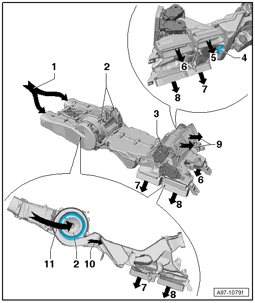
1 - Air Intake from Front Heater and A/C Unit in the Rear Air Distribution Housing
 Note
Note
The temperature of the air flowing from the front heater and A/C unit to the rear air distribution housing, is regulated by the Front A/C Display Control Head -E87- so that the air from the vents in the front area has an average temperature. The target temperature for the air from the vents in the front area is calculated via the setting for the left and right side on the Front A/C Display Control Head -E87- and the Rear A/C Display Control Head -E265- from the Front A/C Display Control Head -E87-. However, if a setting which no longer regulates the temperature (for example, "HI" for maximum heating or "LO" for maximum cooling) is present on the Front A/C Display Control Head -E87-, the temperature of the air from the vents in the front area is no longer regulated. If, for example, maximum heating "HI" is set on the Front A/C Display Control Head -E87- for one side and maximum cooling "LO" for the other side, the air for the vents in the front area is maximally heated.
2 - Rear Fresh Air Blower -V80-
- Refer to → Chapter "Rear Fresh Air Blower -V80-, Removing and Installing"
- Check. Refer to Vehicle Diagnostic Tester in the "Guided Fault Finding" function
3 - Rear Air Distribution Housing
- Refer to → Chapter "Rear Air Distribution Housing Components, Mid or Mix A/C System"
4 - Rear Upper Body Vent Temperature Sensor -G537-
5 - Air Outlet to the Footwell Vent under the Right Seat (Front Passenger Seat)
6 - Air Outlet to the Vent in the Right B-Pillar
7 - Air Outlet to the Footwell Vent under the Left Seat (Driver Seat)
8 - Air Outlet to the Vent in the Left B-Pillar
9 - Air Outlet to the Vent in the Center Console
10 - Air Outlet from the Rear Fresh Air Blower -V80- to the Distribution Housing
11 - Air Inlet into the Rear Fresh Air Blower -V80-
Air Duct in the Rear Heater and A/C Unit, "High" A/C System
 Note
Note
- Depending on vehicle equipment, there are different versions of the A/C system for the Audi Q7. Make sure to use the correct version and pay attention to the allocation of different components. Refer to → Chapter "A/C System Versions" and Parts Catalog.
- The rear heater and A/C unit and the Rear A/C Display Control Head -E265- are optional equipment (only installed on a "High" A/C system).
- The temperature of the air from the rear vent is regulated from the Rear A/C Display Control Head -E265- via various settings and measured values. Refer to Vehicle Diagnostic Tester in the "Guided Fault Finding" function.
- The various doors in the rear heater and A/C unit vents are activated via adjustment motors activated by the Rear A/C Display Control Head -E265-. Refer to → Chapter "Component Location Overview - Rear Adjustment Motor". Refer to Vehicle Diagnostic Tester in the "Guided Fault Finding" function.
- Incorporation of rear A/C unit into cooling- and refrigerant circuit. Refer to → Chapter "Rear Heating and A/C system, Incorporation in the Coolant Circuit, High A/C System".
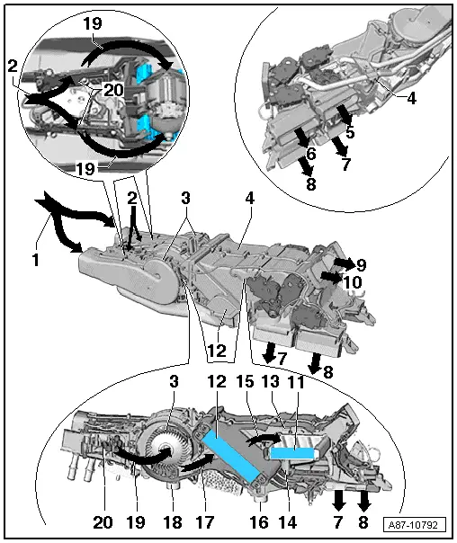
1 - Air Intake from the Front Heater and A/C Unit in the Rear Heater and A/C Unit (Fresh Air Mode)
2 - Air Inlet from the Area under the Center Console (Recirculation Mode)
3 - Rear Fresh Air Blower -V80-
- Refer to → Chapter "Rear Fresh Air Blower -V80-, Removing and Installing"
- Check. Refer to Vehicle Diagnostic Tester in the "Guided Fault Finding" function
4 - Rear Heater and A/C Unit
- Refer to → Chapter "Component Location Overview - Rear Adjustment Motor"
5 - Air Outlet to the Footwell Vent under the Right Seat (Front Passenger Seat)
6 - Air Outlet to the Vent in the Right B-Pillar
7 - Air Outlet to the Footwell Vent under the Left Seat (Driver Seat)
8 - Air Outlet to the Vent in the Left B-Pillar
9 - Air Outlet to the Vent in the Right Center Console
10 - Air Outlet to the Vent in the Left Center Console
11 - Heat Exchanger inside the Rear Heater and A/C unit
- Refer to → Chapter "Heater Core, Removing and Installing"
12 - Evaporator in the Rear Heater and A/C unit
- Removing and installing (only possible with the rear heater and A/C unit removed). Refer to → Chapter "Evaporator, Removing and Installing".
13 - Upper Temperature Door
- The temperature door is shown in the "heat" position
- For separate regulation of the temperature of the air from the left and right vents, a temperature door is installed on the left and on the right side.
- The upper temperature door and lower temperature door of one side are each operated by one control motor. They are connected by a curved washer and an actuating arm. Refer to → Chapter "Component Location Overview - Rear Adjustment Motor".
14 - Lower Temperature Door
- The temperature door is shown in the "heat" position
- For separate regulation of the temperature of the air from the left and right vents, two temperature doors are installed on the left and on the right side.
- The upper temperature door and lower temperature door of one side are each operated by one control motor. They are connected by a curved washer and an actuating arm. Refer to → Chapter "Component Location Overview - Rear Adjustment Motor".
15 - Air Outlet from the Evaporator
- To the heater core in this case since the temperature doors are shown in the "heat" position
16 - Condensation Water Drain under the Evaporator
17 - Air Outlet from the Rear Fresh Air Blower -V80- into the Evaporator
18 - Condensation Water Drain under the Rear Fresh Air Blower -V80-.
19 - Air Inlet into the Rear Fresh Air Blower -V80-
- Depending on the position of the recirculation doors from the front heater and A/C unit or from the area under the center console
20 - Air Recirculation Door in the Rear Heater and A/C Unit
- In this figure both recirculation doors are shown in the "air intake from the front heater and A/C unit" position.
- Both recirculation doors are controlled by the Rear Recirculation Door Motor -V421- which is activated by the Rear A/C Display Control Head -E265-.
- When the recirculation doors are open, the air from the Rear Fresh Air Blower -V80- is not drawn in from the front heater and A/C unit but from under the center console.
