Audi Q7: Overview - Driveshaft
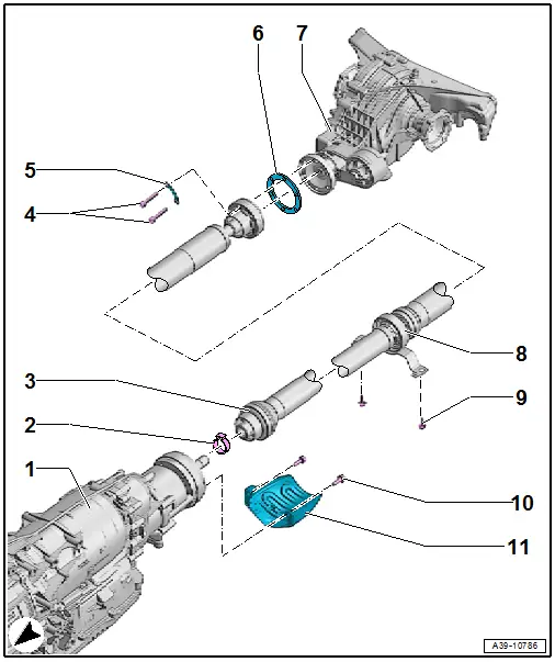
1 - Transmission
2 - Hose Clamp
- Replacing
3 - Driveshaft
- Removing and installing. Refer to → Chapter "Driveshaft, Removing and Installing".
- Removing and installing on the rear final drive. Refer to → Chapter "Drive Shaft, Removing from Rear Final Drive and Installing".
- Replace the boot. Refer to → Chapter "Boot, Replacing".
4 - Bolt
- Tightening specification and sequence. Refer to → Fig. "Driveshaft to Rear Final Drive - Tightening Specification and Sequence".
- Always replace.
- The threads in the flange shaft on the rear final drive must be cleaned of locking fluid residue. Use a thread tap to clean.
- Self-locking
5 - Locking Plate
6 - Seal
- Replace a damaged seal.
- A seal for which the rubber coating has come loose must be replaced
- Clean the flange shaft and position the seal
- Pay no attention to the different colored sides for the installation
7 - Rear Final Drive
- Removing and installing. Refer to → Chapter "Final Drive".
8 - Intermediate Bearing
- Install the alignment pin in the hole on the underbody and tighten.
9 - Bolt
- 20 Nm
10 - Bolt
- 28 Nm
11 - Heat Shield
- Not installed on all versions
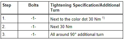
Driveshaft to Rear Final Drive - Tightening Specification and Sequence
- Always replace the driveshaft bolts -1-.
- Counterhold with -T10172- and -T10172/5-.
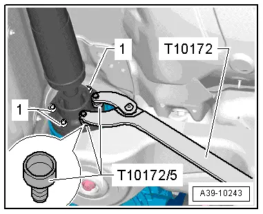
- Tighten the bolts -1- in three steps:
1) By doing this, the CV joint is pushed slightly to the opposite side and imbalance is avoided.
Driveshaft, Removing and Installing
Driveshaft, Removing and Installing, Audi A4
Special tools and workshop equipment required
- Counterhold - Kit - Multiple Use -T10172-
- Counterhold - Kit - Adapter 5 -T10172/5-
- Hose Clip Pliers -VAG1275A-
- High Temperature Grease -G 052 133 A3-
 Caution
This procedure contains mandatory replaceable parts. Refer to component overview prior to starting procedure.
Mandatory Replacement Parts
- Hose Clamp - Driveshaft to Transmission
- Bolts - Driveshaft to Rear Final Drive
Removing
Note the Information about the Driveshaft
- Pay attention to the general repair information. Refer to → Chapter "Repair Information".
- The attached driveshaft can only be separated from the transmission if it is completely removed.
- Always remove or install the driveshaft horizontally from the transmission output shaft.
- Always store and transport the driveshaft when it is fully extended.
- The driveshaft can be bent all the way to the center joint without force. Bending the joint forcibly all the way can damage the center joint and/or the protective boot.
- If the driveshaft is separated only from the rear final drive, the driveshaft must be tied up or supported. If necessary, the driveshaft can be bent as far as the end stop of the center without force.
- Pay attention to the tightening sequence for the driveshaft bolt on the rear final drive. Refer to → Fig. "Driveshaft to Rear Final Drive - Tightening Specification and Sequence".
Should There Be Complaints (Noise, Vibration), Do the following before Replacing the Driveshaft
- Remove all the driveshaft bolts from the rear final drive.
- Tighten the driveshaft with new bolts according to the tightening sequence. Refer to → Fig. "Driveshaft to Rear Final Drive - Tightening Specification and Sequence".
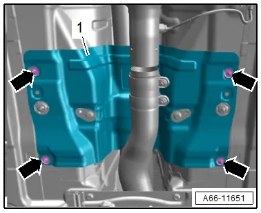
- Remove the bolts -arrows- and the tunnel brace -1-.

 NOTICE
Incorrect handling can damage the coupling.
- Do not bend the coupling more than 10º.
- Do not load the coupling.
- Loosen the lock washer(s) -arrows- and separate the exhaust system.
- Tie up the front exhaust pipe(s) on the side to the underbody.
- Remove the exhaust system rear section.

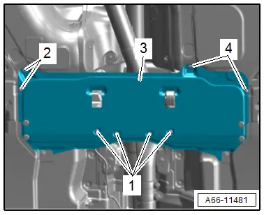
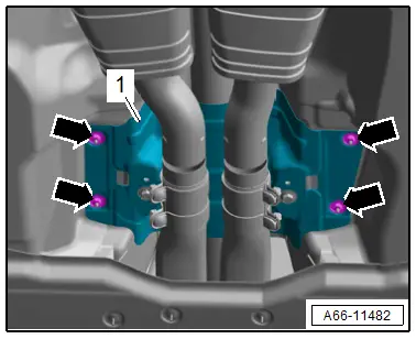
- Loosen the nuts -arrows- and remove the heat shield -1-.
- Remove the bolts -arrows- and remove the driveshaft heat shield -1- (if equipped).

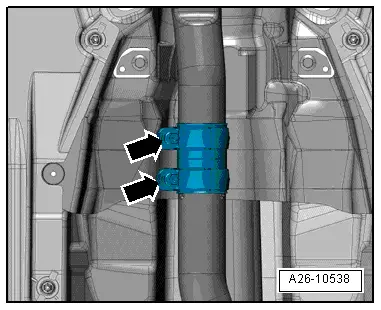
- Cut the hose clamp -1- for the driveshaft boot and remove it.
- Check if there is a mark (color dot) on the driveshaft and on the rear final drive driveshaft flange -arrow A- and -arrow B-.
- Make a color dot again if the original mark is no longer visible.
- The marks on the driveshaft -arrow A- and on the rear final drive -arrow B- must line up.

- Remove the driveshaft bolts -1- from the rear final drive.
- Counterhold with -T10172- and -T10172/5-.

- Remove the driveshaft intermediate bearing mounting bolts -arrows-.
- Push the driveshaft forward and at the same time remove it from the rear final drive.
- Remove the driveshaft from the transmission.

Installing
Install in reverse order of removal. Note the following:
- Tightening specifications. Refer to → Chapter "Overview - Driveshaft".
Driveshaft Information
- Remove any old, dry high-temperature grease from the CV joint and the driveshaft flange. Insert the same quantity of High Temperature Grease -G 052 133 A3-.
- The threads in the flange shaft on the rear final drive must be cleaned of locking fluid residue. They can be cleaned with a thread tap. If the threads are not clean, the bolts will break off when they are being installed.
- Replace the self-locking driveshaft bolts.
- Check the driveshaft seal on the rear final drive flange for damage (bent, rubber layer worn off) and replace if damaged. Replace the damaged seal.
- Wipe the splines on the transmission output shaft with a towel before installing the driveshaft. The splines are not lubricated.
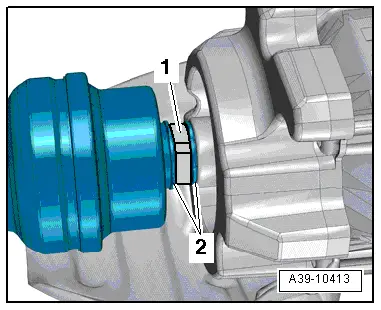
- Replace the hose clamps -1- for the driveshaft boot -2-.
- First mount the driveshaft on the transmission.
- Maximum bend angle: 10º.
- After the driveshaft is inserted approximately 50 mm into the transmission output shaft, turn the driveshaft slightly to make sure that the transmission output shaft splines are meshed into the inner splines of the driveshaft.
- Push the driveshaft all the way onto the splines on the transmission output shaft.

- Attach the driveshaft intermediate bearing to the body so that it is free of tension -arrows-.

- Replace the driveshaft flange seal for the driveshaft.
- Position the driveshaft on the rear final drive while paying attention to the installation position:
- The marks on the driveshaft -arrow A- and on the rear final drive -arrow B- must line up.
- Maximum difference between the markings: 30º.

- Install all six driveshaft bolts -1- by hand all the way but do not tighten.
- Tighten the driveshaft bolts -1- according to the tightening sequence. Refer to → Fig. "Driveshaft to Rear Final Drive - Tightening Specification and Sequence".

- Line up the hose clamp -1- for the driveshaft boot with the retainers -2- and then tighten the clamp using for example the -VAG1275A-.

Tip:
- In order to use the -VAG1275A- correctly, move the driveshaft a little toward the rear.
- Tighten the heat shield -1- to the transmission -arrows-.

- Install the heat shield -1-. Refer to → Body Exterior; Rep. Gr.66; Underbody Trim Panel; Overview - Underbody Trim Panels.

- Install the exhaust system and align it without tension. Refer to → Rep. Gr.26; Exhaust Pipes/Mufflers; Overview - Muffler
- Install the crossmember -1-. Refer to → Body Exterior; Rep. Gr.66; Underbody Trim Panel; Overview - Underbody Trim Panels.
Driveshaft, Removing and Installing, Audi Q7
Special tools and workshop equipment required
- Counterhold - Kit - Multiple Use -T10172-
- Counterhold - Kit - Adapter 5 -T10172/5-
- Hose Clip Pliers -VAG1275A-
- High Temperature Grease -G 052 133 A3-
 Caution
This procedure contains mandatory replaceable parts. Refer to component overview prior to starting procedure.
Mandatory Replacement Parts
- Hose Clamp - Driveshaft to Transmission
- Bolts - Driveshaft to Rear Final Drive
Removing
Note the Information about the Driveshaft
- Pay attention to the general repair information. Refer to → Chapter "Repair Information".
- The attached driveshaft can only be separated from the transmission if it is completely removed.
- Always remove or install the driveshaft horizontally from the transmission output shaft.
- Always store and transport the driveshaft when it is fully extended.
- The driveshaft can be bent all the way to the center joint without force. Bending the joint forcibly all the way can damage the center joint and/or the protective boot.
- If the driveshaft is separated only from the rear final drive, the driveshaft must be tied up or supported. If necessary, the driveshaft can be bent as far as the end stop of the center without force.
- Pay attention to the tightening sequence for the driveshaft bolt on the rear final drive. Refer to → Fig. "Driveshaft to Rear Final Drive - Tightening Specification and Sequence".
Should There Be Complaints (Noise, Vibration), Do the following before Replacing the Driveshaft
- Remove all the driveshaft bolts from the rear final drive.
- Tighten the driveshaft with new bolts according to the tightening sequence. Refer to → Fig. "Driveshaft to Rear Final Drive - Tightening Specification and Sequence".
- Remove the center underbody trim panel. Refer to → Body Exterior; Rep. Gr.66; Underbody Trim Panel; Underbody Trim Panels, Removing and Installing.
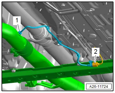
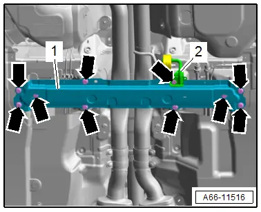
- If equipped, disconnect the connector -2- for the Exhaust Gas Temperature Sensor 5 -G815- and free up the cable.
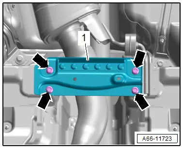
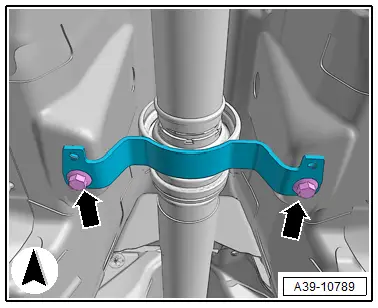
- Remove the bolts -arrows- and the crossmember -1-.
 NOTICE
Incorrect handling can damage the coupling.
- Do not bend the coupling more than 10º.
- Do not load the coupling.
- Loosen the lock washer(s) -arrows- and separate the exhaust system.
- Tie up the front exhaust pipe(s) on the side to the underbody.
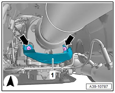
- Loosen the nuts -arrows- and remove the heat shield -1-.

- Remove the bolts -arrows- and remove the driveshaft heat shield -1-.
- Cut the hose clamp -1- for the driveshaft boot and remove it.

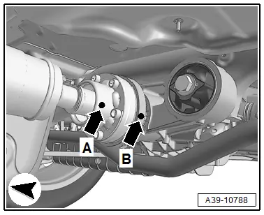
- Check if there is a mark (color dot) on the driveshaft and on the rear final drive driveshaft flange -arrow A- and -arrow B-.
- Make a color dot again if the original mark is no longer visible.
- The marks on the driveshaft -arrow A- and on the rear final drive -arrow B- must line up.
- Remove the driveshaft bolts -1- from the rear final drive.
- Counterhold with -T10172- and -T10172/5-.

- Remove the driveshaft intermediate bearing mounting bolts -arrows-.
- Push the driveshaft forward and at the same time remove it from the rear final drive.
- Remove the driveshaft from the transmission.
Installing
Install in reverse order of removal. Note the following:
- Tightening specifications. Refer to → Chapter "Overview - Driveshaft".
Driveshaft Information
- Remove any old, dry high-temperature grease from the CV joint and the driveshaft flange. Insert the same quantity of High Temperature Grease -G 052 133 A3-.
- The threads in the flange shaft on the rear final drive must be cleaned of locking fluid residue. They can be cleaned with a thread tap. If the threads are not clean, the bolts will break off when they are being installed.
- Replace the self-locking driveshaft bolts.
- Check the driveshaft seal on the rear final drive flange for damage (bent, rubber layer worn off) and replace if damaged. Replace the damaged seal.
- Wipe the splines on the transmission output shaft with a towel before installing the driveshaft. The splines are not lubricated.
- Replace the hose clamps -1- for the driveshaft boot -2-.
- First mount the driveshaft on the transmission.
- Maximum bend angle: 10º.
- After the driveshaft is inserted approximately 50 mm into the transmission output shaft, turn the driveshaft slightly to make sure that the transmission output shaft splines are meshed into the inner splines of the driveshaft.
- Push the driveshaft all the way onto the splines on the transmission output shaft.

- Attach the driveshaft intermediate bearing to the body so that it is free of tension -arrows-.

- Replace the driveshaft flange seal for the driveshaft.
- Position the driveshaft on the rear final drive while paying attention to the installation position:
- The marks on the driveshaft -arrow A- and on the rear final drive -arrow B- must line up.
- Maximum difference between the markings: 30º.

- Install all six driveshaft bolts -1- by hand all the way but do not tighten.
- Tighten the driveshaft bolts -1- according to the tightening sequence. Refer to → Fig. "Driveshaft to Rear Final Drive - Tightening Specification and Sequence".

- Line up the hose clamp -1- for the driveshaft boot with the retainers -2- and then tighten the clamp using for example the -VAG1275A-.

Tip:
- In order to use the -VAG1275A- correctly, move the driveshaft a little toward the rear.
- Tighten the heat shield -1- on the transmission -arrows-.

- Install the heat shield -1-. Refer to → Body Exterior; Rep. Gr.66; Underbody Trim Panel; Overview - Underbody Trim Panels.
- Install the crossmember -1-. Refer to → Body Exterior; Rep. Gr.66; Underbody Trim Panel; Overview - Underbody Trim Panels.
- Install the center underbody trim panel. Refer to → Body Exterior; Rep. Gr.66; Underbody Trim Panel; Underbody Trim Panels, Removing and Installing.
- Install the exhaust system and align it without tension. Refer to → Rep. Gr.26; Exhaust Pipes/Mufflers; Overview - Muffler.

Drive Shaft, Removing from Rear Final Drive and Installing
Special tools and workshop equipment required
- Counterhold - Kit - Multiple Use -T10172-
- Counterhold - Kit - Adapter 5 -T10172/5- (M8 Bolts)
- High Temperature Grease -G 000 633-
 Caution
This procedure contains mandatory replaceable parts. Refer to component overview prior to starting procedure.
Mandatory Replacement Parts
- Hose Clamp - Driveshaft to Transmission
- Bolts - Driveshaft to Rear Final Drive
- Pay attention to the general repair information. Refer to → Chapter "Repair Information".
- The driveshaft can be bent all the way to the center joint without force. Bending the joint forcibly all the way can damage the center joint and/or the protective boot.
- If the driveshaft is separated only from the rear final drive, the driveshaft must be tied up or supported. If necessary, the driveshaft can be bent as far as the end stop of the center without force.
- Pay attention to the tightening sequence for the driveshaft bolt on the rear final drive. Refer to → Fig. "Driveshaft to Rear Final Drive - Tightening Specification and Sequence".
Drive Shaft, Removing from Rear Final Drive
- Check whether there is a color marking on the driveshaft and at flange/driveshaft on the rear final drive -arrow A- and -arrow B-.
- If one of these markings is no longer visible (for example -arrow A- on the driveshaft), then make a mark for the missing colored dot in color.
- The mark on the driveshaft -arrow A- and on the rear final drive -arrow B- line up.

- Remove the bolts -1- (quantity: 6) from the rear CV joint.
- Counterhold with -T10172- and -T10172/5-.
- Remove the driveshaft from the rear final drive and tie up to the underbody or to the exhaust system.

Install the Driveshaft on the Rear Final Drive.
- Remove the old, dry High Temperature Grease from the CV joint and the driveshaft flange. Insert the same quantity of High Temperature Grease -G 000 633-.
- The threads in the flange shaft on the rear final drive must be cleaned of locking fluid residue. They can be cleaned with a thread tap. If the threads are not clean, the bolts will break off when they are being installed.
- Always replace the bolts for driveshaft (self-locking bolts).
- Check the driveshaft seal on the rear final drive flange for damage (bent, rubber layer worn off) and replace if damaged. Replace the damaged seal.

- Replace the driveshaft flange seal for the driveshaft.
- Position the driveshaft on the rear final drive while paying attention to the installation position:
- The marks on the driveshaft -arrow A- and on the rear final drive -arrow B- must line up.
- Maximum difference between the markings: 30º.

- Install all six driveshaft bolts -1- by hand all the way but do not tighten.
- Tighten the driveshaft bolts -1- according to the tightening sequence. Refer to → Fig. "Driveshaft to Rear Final Drive - Tightening Specification and Sequence".


