Audi Q7: Boot, Replacing
Special tools and workshop equipment required
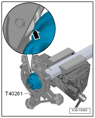
- Flanging Tool -T40261-
- Hose Clamp -23 to 35 mm Diameter-
 Caution
This procedure contains mandatory replaceable parts. Refer to component overview prior to starting procedure.
Mandatory Replacement Parts
- O-ring - Driveshaft joint
Procedure
- Remove the driveshaft. Refer to → Chapter "Driveshaft, Removing and Installing".
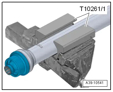
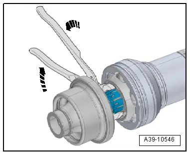
- Clamp the driveshaft with the -T40261/1- into the vise, as shown.
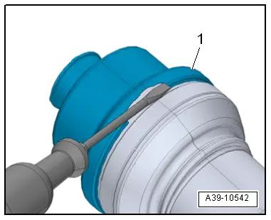
- Carefully loosen the metal sleeve flanging -1- from the driveshaft joint at one place with a screwdriver.
- The surface on the driveshaft joint must not be damaged.
- Open the rest of the metal sleeve flanging in direction of -arrow- with a side cutter.
- Remove the old boot with the metal sleeve from the driveshaft joint.
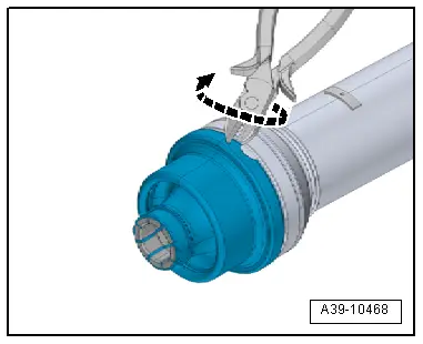
- Break the support ring with the water pump pliers in direction of -arrows- and remove the boot with the metal sleeve.
- The inside of the joint and the balls remain in the driveshaft joint.
- Wipe away any excess grease.
- Grease the driveshaft joint with grease from the installation kit.
- Fill with the same amount of grease, that has been clean off plus the amount that remains in the old boot.
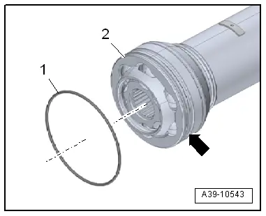
- Clean the sealing surface -arrow- on the driveshaft joint -2-.
- If there are scratches left behind after removing the old boot, smooth them out.
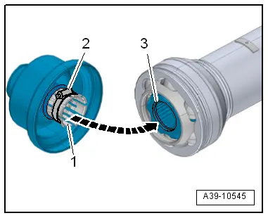
- Insert a new O-ring -1- in the groove.
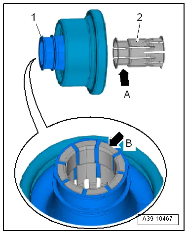
- Install the support ring -2- in the boot opening -1-.
- Direction of installation: the depression -arrow A- is slid into the boot.
- The guides for the support ring -arrow B- must be visible on the edge of the boot opening.
- Fold the boot -2- inward inside the metal sleeve -1-.
- Slide the hose clamp -arrow- onto the open guides for the support ring -3- as shown.
- The end of the support ring must be freed up.
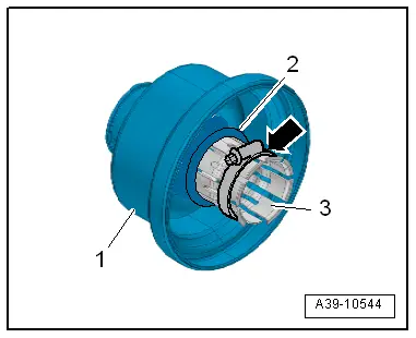
- Tighten the hose clamp -2- until the support ring guides -1- are able to be inserted into the groove -3- of the inside of the joint.
- Loosen the hose clamp -2- and remove.
- The support ring guides must catch on the inside of the groove -arrow-.
- Slide the metal sleeve for the boot all the way onto the joint.
- Attach the -T40261- to the metal sleeve so that the guide roller stops -arrow- are touching the edge of the metal sleeve.
- Flange the metal sleeve by turning the -T40261- back and forth.
- The turning angle must be at least 90º when turning it back and forth.
- While turning it back and forth, turn the hand wheel for the -T40261-.
- The flanging is finished when the hand wheel for the -T40261- can only be turned if a lot of force is used.