Audi Q7: A/C Compressor Regulator Valve -N280-, Checking
A/C Compressor Regulator Valve -N280-, Checking Switch-On Signal
 Note
Note
- The test for an A/C compressor manufactured by "Denso" of type "6 SEU 14" is described in the following. The test is to be performed in the same way for vehicles with a different compressor type or a different manufacturer.
- Certain malfunctions at the A/C Compressor Regulator Valve -N280- (for example, a stuck valve or a short circuit in the coil) can lead to a complaint regarding the A/C compressor (A/C system is not cooling, the evaporator ices over, etc.). If the cause is with the A/C compressor regulator valve -N280- (and not the A/C compressor itself), the A/C compressor can be serviced by replacing the valve -N280-. Refer to → Refrigerant R134a Servicing; Rep. Gr.87; Refrigerant Circuit Components, Replacing.
- The A/C Compressor Regulator Valve -N280- is not available as a replacement part for all A/C compressors. If the A/C Compressor Regulator Valve -N280- is not available as an individual A/C compressor part (different versions), then the entire A/C compressor must be replaced if there is a complaint. Refer to the Parts Catalog.
Preparation
- Turn off the ignition.
- Remove the front noise insulation. Refer to → Body Exterior; Rep. Gr.66; Noise Insulation; Noise Insulation, Removing and Installing.
Test Sequence
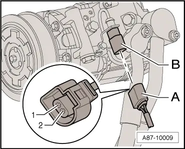
- Connect electrical harness connector -A and B- to the A/C Compressor Regulator Valve -N280-.
- Re-establish the connection between the connector -A- and connector -B- on the A/C Compressor Regulator Valve -N280- using an adapter cable from the Connector Test Set -VAG1594D-.
 Note
Note
- The activation of the A/C Compressor Regulator Valve -N280- takes place via the Vehicle Electrical System Control Module -J519- at the request of the Front A/C Display Control Head -E87- in the "Guided Fault Finding" function. Refer to → Wiring diagrams, Troubleshooting & Component locations.
- The above figure shows an A/C compressor where connector -A- to the vehicle wiring harness is connected directly to the A/C compressor regulator valve -N280- (connector -B-). Depending on the version of the A/C compressor, the connector -B- may also have a short wire.
- The activation of the A/C compressor regulator valve -N280- is displayed in the "read measured values" function of the Guided Fault Finding of the Vehicle Electrical System Control Module -J519- and the Front A/C Display Control Head -E87-. The maximum control current depends on the version of the Front A/C Display Control Head -E87-. Refer to Vehicle Diagnostic Tester in the "Guided Fault Finding" function and refer to → Wiring diagrams, Troubleshooting & Component locations.
- The measured current flowing through the A/C Compressor Regulator Valve -N280- is displayed in the "read measured values" function of the Guided Fault Finding of the Front A/C Display Control Head -E87- and in the "read measured values" function of the Guided Fault Finding of the Vehicle Electrical System Control Module -J519-. Refer to Vehicle Diagnostic Tester in the "Guided Fault Finding" function.
- If the required actual current is not flowing through the A/C Compressor Regulator Valve -N280-, check the positive and ground connections of the Vehicle Electrical System Control Module -J519 - and the wire connections between the Vehicle Electrical System Control Module -J519- and the A/C Compressor Regulator Valve -N280- for short circuit. For contact resistance and interchanged wires according to the wiring diagram. Refer to → Wiring diagrams, Troubleshooting & Component locations.

- An adapter cable can also be used for this test. To do this, for example use one connector each -A and B- (part number 1J0 973 702 and 1J0 973 802 and related terminal contacts), two standard sockets for banana connectors -C- and two wires with 0.5 mm 2 diameter.
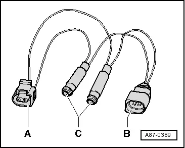
- Connect the Probe -VAS5051/8- to the adapter cables.
- Measuring lead (signal wire) to terminal -2- of connector -B-
- Measuring lead (shielding, Ground) to terminal -1- of connector -B-
- Set the operating mode Test Instruments DSO (digital storage oscilloscope) on the Vehicle Diagnostic Tester. Refer to Vehicle Diagnostic Tester in the function "Guided Fault Finding".
- Select the setting 5V/div = 0.5ms/div (5V DC and 0.5 milliseconds per unit).
- Start the engine.
- Adjust the temperature preset to the maximum cooling output on the Front A/C Display Control Head -E87-.
- Switch activation of the Front A/C Display Control Head -E87- on and off on the A/C Compressor Regulator Valve -N280- by pressing the A/C MAX button with indicator lamp when A/C compressor is on.
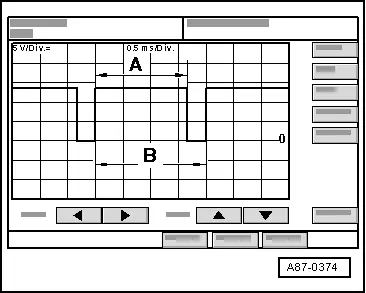
The following is displayed on the oscilloscope screen depending on the Front A/C Display Control Head -E87- setting:
- In operating mode "OFF" or "AC off" indicator lamp in the A/C or A/C MAX button does not illuminate, no square wave signal (the A/C Compressor Regulator Valve -N280- is not activated).
- In operating mode "Auto" and "AC on" (indicator lamps in buttons illuminate) and temperature preselection for maximum cooling, a square wave signal with an impulse width -A- between 75% and 100% (the control valve is activated).
 Note
Note
- The illustration shows a signal with a duty cycle of approximately 80%.
- Impulse width -A- depends on the desired cooling output, vehicle voltage, etc. (over the width of region -A-, the voltage is regulated via the A/C Compressor Regulator Valve -N280- by the Vehicle Electrical System Control Module -J519- on the basis of the request from the Front A/C Display Control Head -E87-).
- The signal distance -B- is always two milliseconds (corresponds to frequency of 500 Hertz).
- The duty cycle is determined by the ratio of impulse width -A- and signal distance -B-.
- The impulse width of the square-wave signal changes (duty cycle between 100% and greater than 30%, the Front A/C Display Control Head -E87- is activated so that the required compressor output is obtained to reach the specified temperatures) depending on the setting on the A/C Compressor Regulator Valve -N280- and the measured environmental conditions.
 Note
Note
- The A/C compressor regulator valve -N280- is activated so that the maximum permissible current of approximately 0.65 A flows through the A/C Compressor Regulator Valve -N280- (maximum compressor output) when "Auto" and "AC ON" are set (the indicator lamps in the buttons are on) and the temperature preset is set to "LO".
- In control mode, actuation time is governed by required cooling output and vehicle electrical system voltage, for example. It is however always of sufficient duration to achieve a mean current of 0.3 A.
- Check the activation of the A/C Compressor Regulator Valve -N280-. Refer to → Chapter "A/C Compressor Regulator Valve -N280-, Checking Activation".
A/C Compressor Regulator Valve -N280-, Checking Activation
 Note
Note
- Perform the electrical test of the activation of the A/C Compressor Regulator Valve -N280- as described in the Guided Fault Finding for the A/C system. Refer to Vehicle Diagnostic Tester in the "Guided Fault Finding" function.
- The activation of the A/C Compressor Regulator Valve -N280- occurs via the Vehicle Electrical System Control Module -J519-. Refer to → Wiring diagrams, Troubleshooting & Component locations. The request to activate the A/C Compressor Regulator Valve -N280- and the necessary current to regulate the compressor output to reach the desired temperature at the evaporator. Is sent via the data bus from the Front A/C Display Control Head -E87- to the Vehicle Electrical System Control Module -J519- The Vehicle Electrical System Control Module -J519- then controls the A/C Compressor Regulator Valve -N280-.
- If a malfunction is detected in the activation of the A/C Compressor Regulator Valve -N280-, a malfunction is entered in the event memory of the Vehicle Electrical System Control Module -J519- and the Front A/C Display Control Head -E87-. When reading out the event memory of the Front A/C Display Control Head -E87-, it will be prompted to query the event memory of the Vehicle Electrical System Control Module -J519-. Refer to Vehicle Diagnostic Tester in the "Guided Fault Finding" function.
- The activation of the A/C Compressor Regulator Valve -N280- is displayed in the "read measured values" function of the Guided Fault Finding of the Vehicle Electrical System Control Module -J519-. Refer to Vehicle Diagnostic Tester in the "Guided Fault Finding" function.
- Certain malfunctions at the A/C Compressor Regulator Valve -N280- (for example, a stuck valve or a short circuit in the coil) can lead to a complaint regarding the A/C compressor (A/C system is not cooling, the evaporator ices over, etc.). If the cause is with the A/C compressor regulator valve -N280- (and not the A/C compressor itself), the A/C compressor can be serviced by replacing the valve -N280-. Refer to → Refrigerant R134a Servicing; Rep. Gr.87; Refrigerant Circuit Components, Replacing.
- The A/C Compressor Regulator Valve -N280- is not available as a replacement part for all A/C compressors. If the A/C Compressor Regulator Valve -N280- is not available as an individual A/C compressor part (different versions), then the entire A/C compressor must be replaced if there is a complaint. Refer to the Parts Catalog.

