Audi Q7: Subframe with Steering Gear, Removing and Installing
Special tools and workshop equipment required
- Torque Wrench 1331 5-50Nm -VAG1331-
- Torque Wrench 1332 40-200Nm -VAG1332-
- Engine and Gearbox Jack -VAS6931-
- Ball Joint Splitter -VAS251805-
- Tensioning Strap -T10038-
- Ball Joint Removal Tool -T10444-
- Gearbox Support -T40173-
Removing
Before starting work:
- Versions with coil springs: determine the curb weight position. Refer to → Chapter "Wheel Bearing in Curb Weight Position, Lifting Vehicles with Coil Spring".
- Versions with air suspension: determine the standard vehicle height. Refer to → Chapter "Wheel Bearing at Standard Vehicle Height, Lifting Vehicles with Air Suspension".
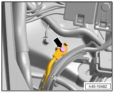
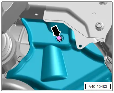
- Remove the bolt -arrow- and free up the ground wire.
- Remove the stabilizer bar. Refer to → Chapter "Stabilizer Bar, Removing and Installing".
- Secure the subframe. Refer to → Chapter "Subframe, Securing".
- Remove the front lower longitudinal member at the left and right. Refer to → Body Exterior; Rep. Gr.63; Front Bumper; Overview - Impact Member.
- Disconnect the left and right connector -3- from the vehicle level sensor and free up the wires.
- Remove the nut -2-, and free up the coupling rod on the control arm.
 Note
Note
Ignore -1-.
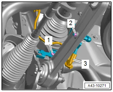
- Remove the bolt -2-.
- Disconnect the connector -3- and free up the wire.
- Remove the bolt -1-.
- Release the catches in direction of -arrows- and free up the bracket -4- for the wires from the subframe.
 Note
Note
The illustration shows the installation position on a vehicle without the parking heater.
- Free up the wire to the steering gear and to the stabilizer bar.
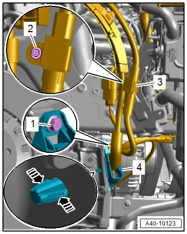
- Disconnect the left and right connector -3- for the electrohydraulic engine mount solenoid valve.
- Remove the connector -2- from the bracket, disconnect it and free up the wire.
- Equipment levels with support bearing: remove the left and right bolt -1- for the support bearing.
- Remove the left and right bolts -arrow- for the subframe shield.
 Caution
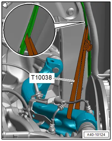
There is a risk of damaging the joints of the upper control arms.
The wheel bearing housing must be supported.
- Tie up the wheel bearing housing on the left and the right with a Tensioning Strap -T10038- as shown.
- To protect the threads remove the nut -arrow- on the left and right on the guide link tie rod head until it is flush with the threads of the joint pin.
 WARNING
Risk of injury from falling components!
When pressing off, the tie rod end loosens abruptly from the wheel bearing housing. Use, for example, the Engine and Gearbox Jack -VAS6931- to secure.
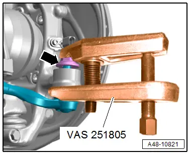
 Caution
There is a risk of damaging the ball joint puller.
Pay attention that both puller lever arms are parallel to each other when using greatest force.
- Remove the left and right tie rod end with the Ball Joint Splitter -VAS251805- from the wheel bearing housing.
- Remove the nut to do so if necessary counterhold on the joint pin with a 6 mm inner hex socket.
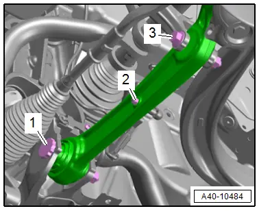
- Disconnect the left and right control arm threaded connections -1 and 3-.
- Pivot the control arm toward the front.
 Note
Note
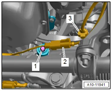
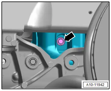
- To remove the bolt -1 -push the steering all the way to the left or right.
- Ignore -2-.
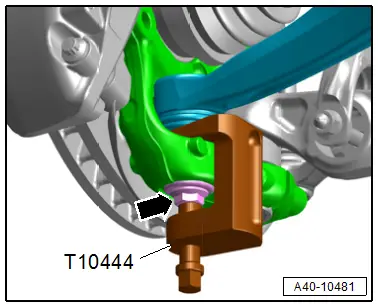
- To protect the threads remove the nut -arrow- on the left and right on the guide link joint pin until it is flush with the threads of the joint pin.
 WARNING
Risk of injury from falling components!
When pressing off, the tie rod end loosens abruptly from the wheel bearing housing. Use, for example, the Engine and Gearbox Jack -VAS6931- to secure.
- Remove the guide link joint pin with the Ball Joint Removal Tool -T10444- from the conical seat, at the same time do not damage the CV boot.
- Remove the nut and free up the guide link on the wheel bearing housing to do so if necessary counterhold the joint pin with a TX 40 socket.
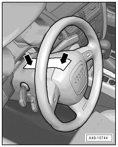
- Secure the steering wheel in the straight-ahead position using adhesive tape so that it does not turn -arrow-.
 Note
Note
- Use adhesive tape, that can be removed without leaving any adhesive residue.
- Be careful not to turn the steering wheel during the repair because the Airbag Spiral Spring/Return Spring with Slip Ring -F138- can become damaged.
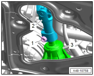
- Remove the bolt -1-.
- Remove the universal joint -2- from the steering gear -3-.
- Remove engine bracket left and right bolt -arrow-.
- Lower the subframe with the Engine and Gearbox Jack -VAS6931-.
 Note
Note
Make sure there is enough clearance for the electric lines when lowering the subframe.
Installing
Install in reverse order of removal and note the following:
Pre-Adjustment of the Subframe:
 Note
Note
Perform a pre-adjustment on the subframe if it is being replaced or if it had to be removed in order to loosen the crossbrace.
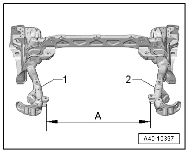
1 - Place the subframe over the head.
2 - Pre-install the steering gear and guide link (at the same time tighten the bolts hand-tight).
3 - Move the arms -1 and 2- to adjust to the dimension -A-. Dimension -A- = inner edges of the holes to each other.
4 - Mount the crossbrace and tighten it to the rear bolting points. The crossbrace is now pre-adjusted.
5 - Tighten the steering gear.
6 - Tighten the crossbrace at the front two attaching points.
- Dimension -A- = 738 mm
Installation Procedure:
- Remove the Locating Pins -T40327-. Refer to → Chapter "Subframe, Securing".
- Install the steering intermediate shaft. Refer to → Chapter "Steering Intermediate Shaft, Removing and Installing".
 Note
Note
Bonded rubber bushings have a limited range of motion. Only tighten suspension bolts when vehicle is in curb weight position or at standard vehicle height.
- Lifting the wheel bearing in curb weight position (refer to → Chapter "Wheel Bearing in Curb Weight Position, Lifting Vehicles with Coil Spring") or at standard vehicle height (refer to → Chapter "Wheel Bearing at Standard Vehicle Height, Lifting Vehicles with Air Suspension").
- Install the stabilizer bar. Refer to → Chapter "Stabilizer Bar, Removing and Installing".
 WARNING
Risk of accident!
If vehicle will be driving on the streets, all bolts and nuts must be tightened properly!
- Connections and wiring routing. Refer to → Wiring diagrams, Troubleshooting & Component locations.
- Overview table for if an axle alignment is necessary. Refer to → Chapter "Need for Axle Alignment, Evaluating".
Versions with Coil Springs:
- Adjust the headlamps. Refer to → Electrical Equipment; Rep. Gr.94; Headlamps; Headlamp, Adjusting.
- Driver Assistance Systems Front Camera, Calibrating. Refer to → Chapter "Driver Assistance Systems Front Camera, Calibrating".
- Infrared System, Calibrating. Refer to → Chapter "Infrared System, Calibrating".
Versions with Air Suspension:
- Readapt the standard vehicle height. Refer to → Chapter "Standard Vehicle Height, Readapting".
Tightening Specifications
- Refer to → Chapter "Overview - Subframe"
- Refer to → Chapter "Overview - Suspension Strut and Upper Control Arm"
- Refer to → Chapter "Overview - Lower Control Arm and Ball Joint"
- Refer to → Chapter "Overview - Wheel Bearing"
- Refer to → Body Exterior; Rep. Gr.63; Front Bumper; Overview - Impact Member.
- Refer to → Body Exterior; Rep. Gr.66; Wheel Housing Liner; Overview - Front Wheel Housing Liner.
- Refer to → Chapter "Wheels and Tires"
Subframe Crossbrace, Removing and Installing
Special tools and workshop equipment required
- Torque Wrench 1331 5-50Nm -VAG1331-
Removing
- Remove the noise insulations. Refer to → Body Exterior; Rep. Gr.66; Noise Insulation; Noise Insulation, Removing and Installing.
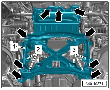
- Versions with side transmission mount: remove the bolts -1 and 3-.
- Remove the bolts -arrows- and the subframe crossbrace -1-.
 Caution
There is a risk of damaging the suspension components.
- If the subframe mount, steering gear or subframe crossbrace are not installed correctly, do not rest the vehicle on its wheels.
- Supporting the vehicle at the subframe or the subframe crossbrace (for example, using a floor jack or similar device) is not permitted.
 Note
Note
If the vehicle must be moved, install the crossbrace for the subframe and tighten the old bolts to the tightening specification without an additional turn.
Installing
Install in reverse order of removal.
Tightening Specifications
- Refer to → Chapter "Overview - Subframe"
- Refer to → Body Exterior; Rep. Gr.66; Noise Insulation; Overview - Noise Insulation.
Subframe Shield, Removing and Installing
One-Piece Subframe Shield, Removing and Installing
 Note
Note
The procedure for the left side of the vehicle is described.
Special tools and workshop equipment required
- Torque Wrench 1410 -VAG1410-
Removing
- Versions with 3.0L TFSI engine: remove the rear noise insulation. Refer to → Body Exterior; Rep. Gr.66; Noise Insulation; Noise Insulation, Removing and Installing.
- Versions with 3.0L TDI engine: remove the center noise insulation. Refer to → Body Exterior; Rep. Gr.66; Noise Insulation; Noise Insulation, Removing and Installing.
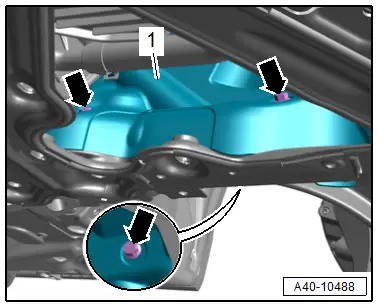
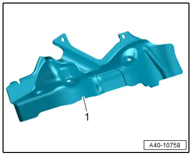
- Push the front wheels to the right.
- Remove the bolts -arrows- and the subframe shield -1-.
Installing
Install in reverse order of removal.
Tightening Specifications
- Refer to → Chapter "Overview - Subframe"
- Refer to → Body Exterior; Rep. Gr.66; Noise Insulation; Overview - Noise Insulation.
Two-Piece Subframe Shield, Removing and Installing
 Note
Note
The procedure for the left side of the vehicle is described.
Special tools and workshop equipment required
- Torque Wrench 1410 -VAG1410-
Shield Upper Section, Removing
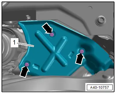
- Push the front wheels to the right.
- Remove the bolts -arrows- and the subframe shield upper section -1-.
Shield Lower Section, Removing
- Remove the left transmission mount. Refer to → Engine Mechanical; Rep. Gr.10; Subframe Mount; Transmission Mount, Removing and Installing.
- Remove the bolts -arrows- and the subframe shield lower section -1-.
Installing
Install in reverse order of removal.
Tightening Specifications
- Refer to → Chapter "Overview - Subframe"

