Audi Q7: Roof Antenna, Removing and Installing
The Roof Antenna -R216- has a maximum of four connections.
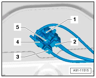
The antenna wires are connected directly to the base of the Roof Antenna -R216-.
The rear headliner must be lowered in order to remove the Roof Antenna -R216-.
Removing
- Turn off the ignition and all electrical equipment and remove the ignition key.
- Lower the back of the headliner. Refer to → Body Interior; Rep. Gr.70; Roof Trim Panels; Headliner, Removing and Installing.
- Unlock and disconnect the connectors -2-, -3- and -4- from the antenna wires.
- Remove the bolt -5- and the retaining spring.
- Remove the Roof Antenna -R216- upward from the roof.
Installing
The Roof Antenna -R216- is supplied pre-assembled. The Roof Antenna -R216-, spring and screw are installed.
- Place the Roof Antenna -R216- on the roof and press down on it until it latches.
- Tighten the pre-mounted bolt to the given tightening specification.
- Install in reverse order of removal.
Tightening Specifications
- Refer to → Chapter "Component Location Overview - Antenna Systems, Europe and Rest of World"
- Refer to → Chapter "Component Location Overview - Antenna Systems, USA"
Bumper Antennas, Removing and Installing
The Telephone Antenna -R65- (Europe and Rest of World)/LTE Antenna 2 -R306- (USA)/LTE Antenna 1 -R297- is located behind the rear bumper trim panel.
Removing
- Turn off the ignition and all electrical equipment and remove the ignition key.
- Remove the rear bumper cover. Refer to → Body Exterior; Rep. Gr.63; Rear Bumper; Bumper Cover, Removing and Installing.
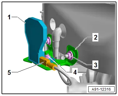
Telephone Antenna -R65-/LTE Antenna 2 -R306- on the rear bumper on the right side
- Release and disconnect the connector -5- for the Telephone Antenna -R65--1-.
- Remove the nut -4- for the Telephone Antenna -R65--1-.
- Remove the Telephone Antenna -R65--1- from the bracket -2-.
- Remove the nuts -3- for the bracket -2-
- Remove the bracket -2- from the body.
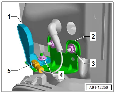
LTE Antenna 1 -R297- on the rear bumper on the left side.
- Release and disconnect the connector -5- for the LTE Antenna 1 -R297--1-.
- Remove the nut -4- for the LTE Antenna 1 -R297--1-.
- Remove the LTE Antenna 1 -R297--1- from the bracket -2-.
- Remove the nuts -3- for the bracket -2-
- Remove the bracket -2- from the body.
Installing
- Install in reverse order of removal.
Tightening Specifications
- Refer to → Chapter "Component Location Overview - Antenna Systems, Europe and Rest of World"
- Refer to → Chapter "Component Location Overview - Antenna Systems, USA"
Emergency Module Antenna, Removing and Installing
Emergency Module Antenna -R263-, Removing and Installing
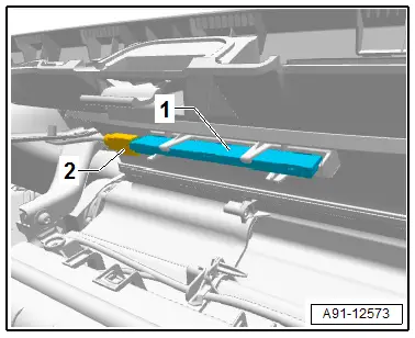
The Emergency Module Antenna -R263- is located in the front center instrument panel (only IW3)
Removing
- Turn off the ignition and all electrical equipment and remove the ignition key.
- Remove the instrument panel. Refer to → Body Interior; Rep. Gr.70; Instrument Panel; Overview - Instrument Panel.
- Disconnect the connector -2-.
- Remove the Emergency Module Antenna -R263--1- from the mount.
Installing
- Install in reverse order of removal.
Emergency Module Antenna -R263-, Removing and Installing, Tinted Glass
The Emergency Module Antenna -R263- is located in the luggage compartment side trim panel on the left side (only IW3)
Removing
- Turn off the ignition and all electrical equipment and remove the ignition key.
- Remove the left luggage compartment side trim panel. Refer to → Body Interior; Rep. Gr.70; Luggage Compartment Trim Panels; Luggage Compartment Side Trim Panel, Removing and Installing.
- Disconnect the connector.
- Remove the Emergency Module Antenna -R263- from the mount.
Installing
- Install in reverse order of removal.

