Audi Q7: Subframe, Securing
Special tools and workshop equipment required
- Torque Wrench 1331 5-50Nm -VAG1331-
- Torque Wrench 1332 40-200Nm -VAG1332-
- Engine and Gearbox Jack -VAS6931-
- Gearbox Support -T40173-
- Locating Pins -T40329-, not illustrated
- Hand drill
- 8.5 mm diameter drill
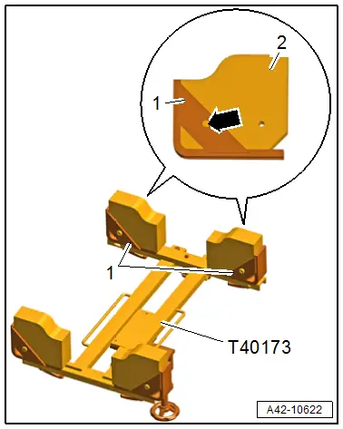
Gearbox Support -T40173-, Preparing
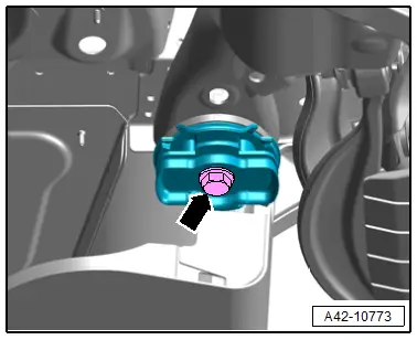
- Remove the mounting elements -1- from the Gearbox Support -T40173-.
- Turn the mounting block -2- as shown and make a 8.5 mm diameter hole -arrow-.
- Secure the mounting bracket with the bolts and move it to the side.
 Note
Note
The mounting elements are mounted on the Gearbox Support -T40173- later.
Procedure
- Remove the rear wheels. Refer to → Chapter "Wheels and Tires".
- Remove the left and right underbody trim panels. Refer to → Body Exterior; Rep. Gr.66; Underbody Trim Panel; Underbody Trim Panels, Removing and Installing.
- Loosen the left and right rear wheel housing liner in the rear area and push slightly to the side. Refer to → Body Exterior; Rep. Gr.66; Wheel Housing Liner; Rear Wheel Housing Liner, Removing and Installing.
- Exhaust system without separating point: remove the muffler. Refer to → 6-Cylinder Direct Injection 3.0L 4V TFSI Supercharged Engine; Rep. Gr.26; Exhaust Pipes/Mufflers; Muffler, Removing and Installing.
- Exhaust system with separating point: remove the exhaust pipe. Refer to → Rep. Gr.26; Exhaust Pipes/Mufflers; Overview - Muffler.
- Versions with air suspension: perform the system bleeding. Refer to → Chapter "Air Suspension System, Filling and Bleeding".
- Remove the left and right spring. Refer to → Chapter "Spring, Removing and Installing".
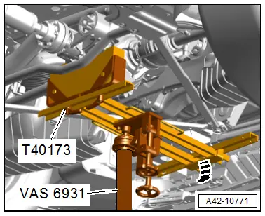
- Angle the Gearbox Support -T40173- with the adjusting bolt toward the rear in direction of -arrow-.
- Support the subframe with the Engine and Gearbox Jack - VAS6931- and the Gearbox Support -T40173- on the rear final drive as shown.
- Remove the diagonal braces. Refer to → Body Exterior; Rep. Gr.66; Underbody Trim Panel.
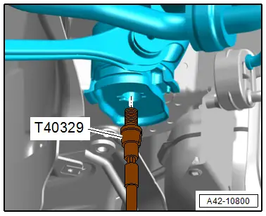
- Tighten the locating pins of the left and right Locating Pins -T40329- in the front bonded rubber bushing to 20 Nm.
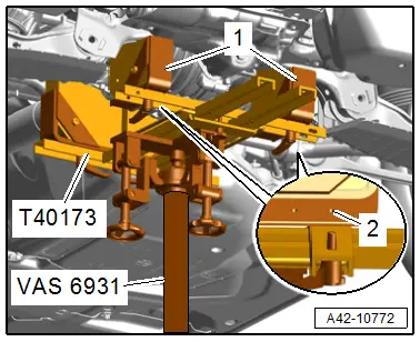
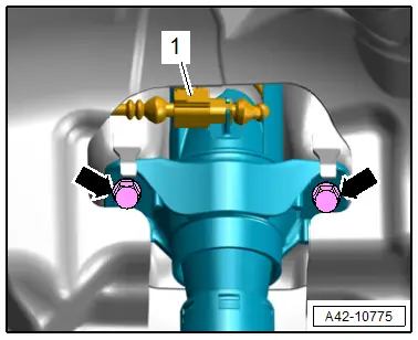
- Mount the prepared mounting element -1- to the threaded hole -2- on the Gearbox Support -T40173- as shown.
- Angle the Gearbox Support -T40173- with the adjusting bolt toward the front until the rear mounting bracket contacts the subframe.
 Note
Note
Compensate the height several times with the Engine and Gearbox Jack -VAS6931-.
- Secure the subframe with the tensioning strap of the engine and gearbox jack.
 Caution
There is a risk of damaging the threads on the subframe threaded connection to the body.
- The subframe bolts on the body must not be loosened or tightened with an impact wrench.
- Always install all bolts by hand for the first few turns.
- Remove the left and right bolts -arrows- one after the other and install a locating pin from the Locating Pins -T40329-.
- Tighten locating pins to 20 Nm.
- The subframe position is now secured.
Remove the Locating Pins -T40329-.
Removal is performed in the reverse order. Note the following:
- Only remove one bolt diagonally and install a new bolt in this location and tighten.
 Caution
There is a risk of damaging the threads on the subframe threaded connection to the body.
- The subframe bolts on the body must not be loosened or tightened with an impact wrench.
- Always install all bolts by hand for the first few turns.
 WARNING
Risk of accident!
If vehicle will be driving on the streets, all bolts and nuts must be tightened properly!
- Install the spring. Refer to → Chapter "Spring, Removing and Installing".
- A road test must be performed after completing repairs. If steering wheel is crooked, the wheels must be aligned. Refer to → Chapter "Vehicle Alignment".
Tightening Specifications
- Refer to → Chapter "Overview - Subframe"
- Diagonal brace. Refer to → Body Exterior; Rep. Gr.66; Underbody Trim Panel.
- Refer to → Rep. Gr.26; Exhaust Pipes/Mufflers; Overview - Muffler.
- Refer to → Body Exterior; Rep. Gr.66; Wheel Housing Liner; Overview - Rear Wheel Housing Liner.
- Refer to → Body Exterior; Rep. Gr.66; Underbody Trim Panel.
- Refer to → Chapter "Wheels and Tires"
Subframe, Removing and Installing
Removing
 Note
Note
If the drive axle/stub shaft threaded connection on the wheel hub is loosened to perform work, this must take place when the vehicle is standing on wheels. Loosen the drive axle threaded connection. Refer to → Chapter "Drive Axle Threaded Connection, Loosening and Tightening".
Before starting work:
- Versions with coil springs: determine the curb weight position. Refer to → Chapter "Wheel Bearing in Curb Weight Position, Lifting Vehicles with Coil Spring".
- Versions with air suspension: determine the standard vehicle height. Refer to → Chapter "Wheel Bearing at Standard Vehicle Height, Lifting Vehicles with Air Suspension".
- Secure the subframe. Refer to → Chapter "Subframe, Securing".
- Remove the left and right rear brake caliper. Refer to → Brake System; Rep. Gr.46; Rear Brakes; Brake Caliper, Removing and Installing.
- Remove the driveshaft from the rear final drive and tie it up. Refer to → Rear Final Drive; Rep. Gr.39; Driveshaft; Driveshaft, Removing and Installing.
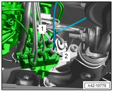
- Disconnect the left and right connector -arrow- from the rear vehicle level sensor and free up the wire.
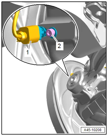
- Disconnect the left and right connector -1- the speed sensor.
 Note
Note
Ignore -2-.
Versions with Air Suspension
- If installed, disconnect the left and right connector -1-.
- Remove the bolts -arrows- on the upper shock absorber fastener.
Vehicles with Rear Axle Steering
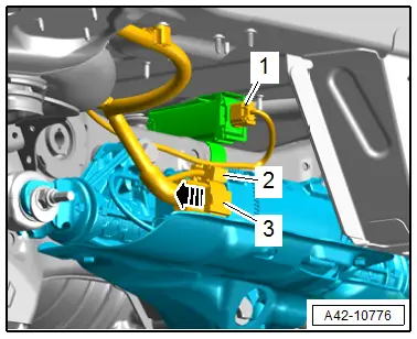
- Release the safety catch in direction of -arrow-, push the retainer down and disconnect the connector from -3- for the Rear Axle Steering Control Module -J1019-.
- Equipped on some models: disconnect the connector -1- for the tire pressure monitoring antenna.
- Free up the wiring harness from the subframe.
Continuation for All Vehicles:
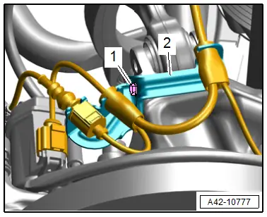
- Equipped on some models: disconnect the connector -1- for the tire pressure monitoring antenna.
- Remove the left and right bolt -1- and free up the bracket -2- with the wires.
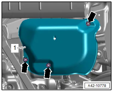
Versions with Air Suspension
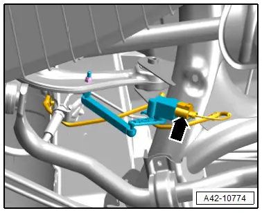
- Remove the nuts -arrows-, and remove the cover -1- for the air supply unit.
- Remove the air lines -1 and 2- with the rear air springs.
Continuation for All Vehicles:
- Carefully lower the subframe.
Installing
Install in reverse order of removal and note the following:
- Tighten the bolts for the subframe and additional turn diagonally.
 WARNING
Risk of accident!
If vehicle will be driving on the streets, all bolts and nuts must be tightened properly!
- A road test must be performed after completing repairs. If steering wheel is crooked, the wheels must be aligned. Refer to → Chapter "Vehicle Alignment".
Tightening Specifications
- Refer to → Chapter "Overview - Subframe"
- Refer to → Chapter "Overview - Transverse Link"
- Refer to → Chapter "Overview - Wheel Bearing"
- Refer to → Chapter "Wheels and Tires"

