Audi Q7: Battery
Overview - Battery
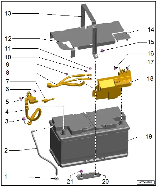
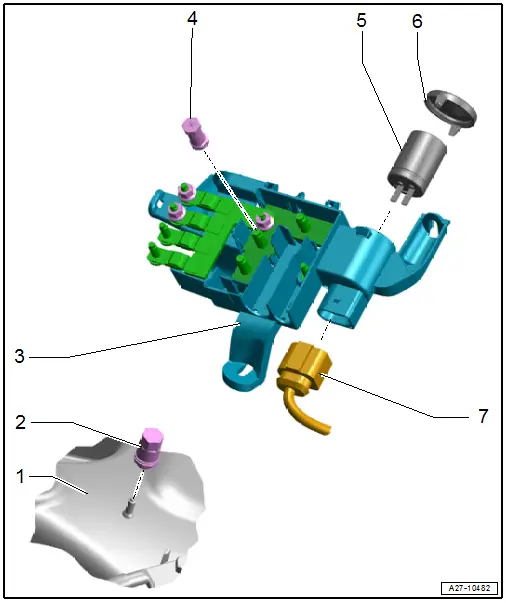
1 - Grommet
- For the central venting system hose
2 - Central Venting System Hose
3 - Nut
- 20 Nm
4 - Ground Wire
- With Battery Monitoring Control Module -J367-
- Disconnecting and connecting. Refer to → Chapter "Battery, Disconnecting and Connecting".
- Removing and installing. Refer to → Chapter "Ground Cable with Battery Monitoring Control Module -J367-, Removing and Installing".
5 - Bolt
6 - Nut
- 5.4 Nm
7 - Wire
- For Battery Monitoring Control Module -J367-
- Follow the sequence when connecting the ground cable.
8 - Positive Cable
- To the engine
9 - Nut
- 18 Nm
10 - Nut
- 7.5 Nm
11 - Nut
- 7.5 Nm
12 - Battery Cover
13 - Retaining Bracket
14 - Positive Terminal Cover
15 - Nut
- 25 Nm
16 - Bolt
17 - Nut
- 5 Nm
18 - Main Fuse Panel
- Disconnecting and connecting. Refer to → Chapter "Battery, Disconnecting and Connecting".
19 - Battery
- Checking. Refer to → Electrical Equipment General Information; Rep. Gr.27; Battery, Checking.
- Removing and installing. Refer to → Chapter "Battery, Removing and Installing".
20 - Battery Bracket
21 - Nut
- 25 Nm
Battery, Disconnecting and Connecting
- After working on pyrotechnic components (such as airbags and belt tensioners), the battery must be disconnected when the ignition is switched on, contrary to the following description.
- After working on the SCR system after switching off the ignition wait until the complete reducing agent has returned.
Disconnecting
- Turn off the ignition.
- Adjust the front passenger seat as far to the rear as possible. Use the entire adjustment range of the seat adjustment for this.
- Remove the floor mat from the front passenger footwell.
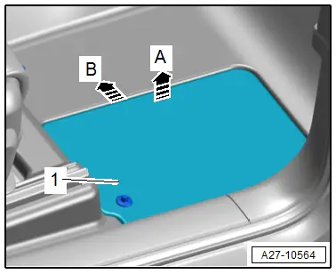
- Release the cover -1- upward in direction of -arrow A- and remove toward the center of the vehicle in direction of -arrow B-.

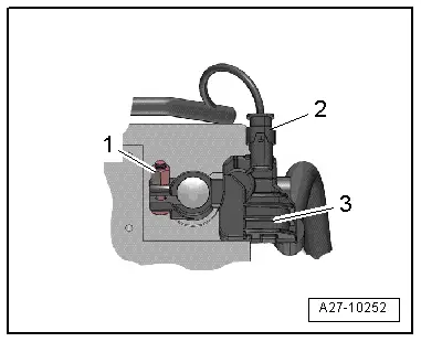
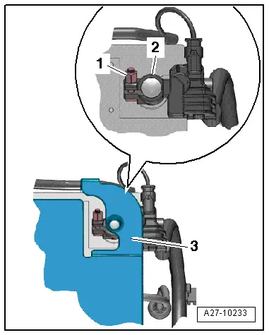
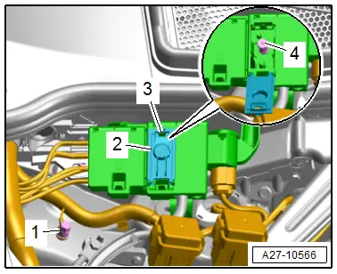
- Open the cover -3- over the battery negative terminal.
- Loosen the nut -1- several turns and remove the battery terminal clamp -2- for the ground cable from the battery terminal.

Connecting
- Disconnect the connector -2- from the Battery Monitoring Control Module -J367--3-.
- Connect the battery ground cable terminal clamp to the battery negative terminal "-" by hand and tighten the nut -1-.
- Reconnect the connector to the Battery Monitoring Control Module -J367-.
When the battery is reconnected, the following steps must be performed:
- Activate the one-touch up/down function of power window regulators. Refer to the Owner's Manual.
- Check DTC memories of all control modules and delete the displayed entry "Undervoltage". Refer to Vehicle Diagnostic Tester.
TIP
After reconnecting the power supply, the ESP warning lamp can only go out after the vehicle has been driven a few meters.
Tightening Specifications
- Refer to → Chapter "Overview - Battery"
Ground Cable with Battery Monitoring Control Module -J367-, Removing and Installing
- After working on pyrotechnic components (such as airbags and belt tensioners), the battery must be disconnected when the ignition is switched on, contrary to the following description.
- After working on the SCR system after switching off the ignition wait until the complete reducing agent has returned.
Removing
- Turn off the ignition.
- Adjust the front passenger seat as far to the rear as possible. Use the entire adjustment range of the seat adjustment for this.
- Remove the floor mat from the front passenger footwell.
- Release the cover -1- upward in direction of -arrow A- and remove toward the center of the vehicle in direction of -arrow B-.

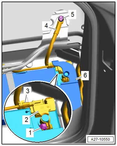
- Open the cover -6- over the battery negative terminal.
- Loosen the nut -1- several turns and remove the battery ground cable terminal clamp from the battery terminal.
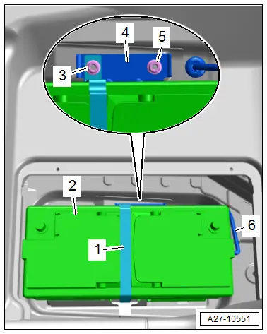
- Disconnect the connector -3-.
- Slightly lift the carpet in the area of the nut.
- Remove the nut -5- and ground cable -4- with the Battery Monitoring Control Module -J367--2-.
Installing
Install in the reverse order of removal while noting the following:
- Connect the battery. Required actions.
Tightening Specifications
- Refer to → Chapter "Overview - Battery"
Battery, Removing and Installing
- If the battery should be replaced, connect the battery charger for battery support mode. Refer to → Electrical Equipment General Information; Rep. Gr.27; Battery, Charging.
- After working on pyrotechnic components (such as airbags and belt tensioners), the battery must be disconnected when the ignition is switched on, contrary to the following description.
- After working on the SCR system after switching off the ignition wait until the complete reducing agent has returned.
Removing
- Turn off the ignition.
- Adjust the front passenger seat as far to the rear as possible. Use the entire adjustment range of the seat adjustment for this.
- Remove the floor mat from the front passenger footwell.
- Release the cover -1- upward in direction of -arrow A- and remove toward the center of the vehicle in direction of -arrow B-.
- Open the cover -3- over the battery negative terminal.
- Loosen the nut -1- several turns and remove the battery terminal clamp -2- for the ground cable from the battery terminal.
- Open the cover -1- over the battery positive terminal.
- Loosen the nut -3- several turns and remove the battery terminal clamp -2- for the positive cable from the battery terminal.

- Remove the nuts -3 and 5-.
- Disengage the retaining bracket -1- on the opposite side.
- Remove the battery bracket -4- upward.
- Remove the battery cover -2-.
- Remove the central venting system hose -6-.
- Lift the battery up and out of the front passenger footwell.
- The disposal regulations for batteries and sulfuric acid must be followed when disposing of batteries. Refer to → Electrical Equipment General Information; Rep. Gr.27; Battery.
Installing
TIP
Batteries from the Audi Parts Program have a base strip adapter for conforming to different clamping strips. See the battery operating instructions for information on when and how to use the base strip adapter.
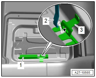
- Push the battery up against the retaining bracket -1- so that the battery clamping strip engages in the retaining bracket.
- The battery must not be able to move at all.
- Engage the retaining bracket -2- in the mount slit -3- on the retaining bracket -arrow-.
- Attach the central venting system hose.
Install in the reverse order of removal. Note the following:
- With the ignition and electrical equipment switched off, connect the battery in the following sequence:
- First connect the battery terminal clamp -2- for the positive cable to the battery positive terminal "+" by hand and tighten the nut -3-.
- Close the cover -1- over the battery positive terminal.
- Disconnect the connector -2- from the Battery Monitoring Control Module -J367--3-.
- Connect the battery terminal clamp for the ground cable to the battery negative terminal "-" by hand and tighten the nut -1-.
- Reconnect the connector to the Battery Monitoring Control Module -J367-.
- Check the battery for secure fit after installation.
- If the battery was replaced, then the new battery must be adapted.

Procedure
- Connect the Vehicle Diagnostic Tester.
- Select the Diagnostic mode and start.
- Select the Test plan tab.
- Press the Select individual tests button and select the following one after the other:
- Body
- Electrical Equipment
- 01 - OBD-capable systems
- 19 - Data Bus On Board Diagnostic Interface - J533
- 19 - Data Bus On Board Diagnostic Interface functions
- 19 - Adapting
- 19 - Adapt battery
- Start the selected program and follow the instructions in the Vehicle Diagnostic Tester display.
When the battery is reconnected, the following steps must be performed:
- Activate the one-touch up/down function of power window regulators. Refer to the Owner's Manual.
- Check all the control module DTC memories and erase the displayed "undervoltage" entry. Refer to Vehicle Diagnostic Tester.
TIP
After reconnecting the power supply, the ESP warning lamp can only go out after the vehicle has been driven a few meters.
Tightening Specifications
- Refer to → Chapter "Overview - Battery"
Battery, Charging
Battery, Preparing for Charging
Procedure
 CAUTION
Risk of explosion due to discharged battery with "visual indicator".
Severe injury possible.
- If the display of the "visual indicator" is colorless or light yellow, do not check, charge or jump start the battery.
- Replace the battery.
TIP
It is recommended that the battery is charged when installed and connected. This is the only way to ensure the charge current is incorporated into the capacity calculation for the Battery Monitoring Control Module -J367-.
Before the battery charger can be connected, the following preliminary work is necessary:
- Turn off the ignition and all electrical equipment.
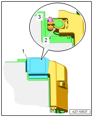
- Open the cover -2-, to do so release the catch -3-.
- Connect the red charging clamp "+" from the battery charger to the positive terminal -4- and the black charging clamp "-" to the negative terminal -1-.
- Connect the battery charger electrical system connector and turn on the battery charger. Refer to → Electrical Equipment General Information; Rep. Gr.27; Battery, Charging.
- Leave the rear lid open while charging the battery.

Battery, Preparing for Support Mode
Procedure
- Open the cover -2-, to do so release the catch -3-.
- Connect the red charging clamp "+" from the battery charger to the positive terminal -4- and the black charging clamp "-" to the negative terminal -1-.
- Connect the battery charger electrical system connector and turn on the battery charger. Refer to → Electrical Equipment General Information; Rep. Gr.27; Battery, Charging.
Battery Cut-Out/Battery Interrupt, Removing and Installing
If the Battery Interrupt Igniter -N253- is faulty or triggered then the main fuse panel on the battery must be replaced.
- Replace the main fuse panel on the battery. Refer to → Chapter "Main Fuse Panel on Battery, Removing and Installing".
Battery Jump Start Terminal
Overview - Battery Jump Start Terminal
1 - Suspension Strut Tower
2 - Negative Terminal
- 9 Nm
3 - Terminal 30 Wire Junction -TV2-
- With jump start point
- Component location overview. Refer to → Chapter "Overview - Component Location Relay Panel, Instrument Panel, E-Boxes Engine Compartment".
4 - Positive Terminal
- 7.5 Nm
5 - Suppressor -C24-
- Component location overview. Refer to → Chapter "Overview - Component Location Relay Panel, Instrument Panel, E-Boxes Engine Compartment".
6 - Cover
7 - Connector

