Audi Q7: Component Location Overview - Gaskets
Audi Q7 (4M) 2016-2025 Workshop Manual / Drivetrain / Rear Final Drive, Differential / Seals / Component Location Overview - Gaskets
Component Location Overview - Gaskets, 0DB and 0D2
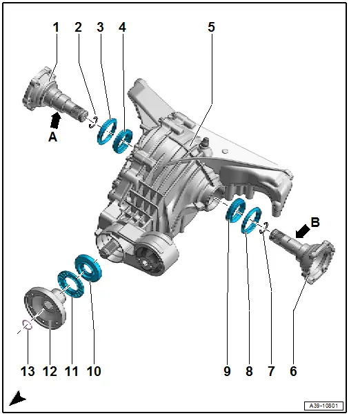
1 - Right Flange Shaft
- Removing and installing. Refer to → Chapter "Right Seal, Replacing".
- Final drive 0DB: the right and left flange shaft are identical
- Final drive 0D2: -Arrow a- shaft diameter approximately 40 mm
2 - Circlip
- Always replace.
3 - Right Protective Ring
- Replacing. Refer to → Chapter "Flange Shaft Protective Ring, Replacing".
4 - Right Seal
- Replacing. Refer to → Chapter "Right Seal, Replacing".
5 - Rear Final Drive
- Refer to → Chapter "Final Drive, Removing and Installing"
6 - Left Flange Shaft
- Removing and installing. Refer to → Chapter "Left Seal, Replacing".
- Final drive 0DB: the right and left flange shaft are identical
- Final drive 0D2: -Arrow B- shaft diameter approximately 32 mm
7 - Circlip
- Always replace.
8 - Left Ring
- Replacing. Refer to → Chapter "Flange Shaft Protective Ring, Replacing".
9 - Left Seal
- Replacing. Refer to → Chapter "Left Seal, Replacing".
10 - Input Shaft Seal
- Replacing. Refer to → Chapter "Input Shaft Seal, Replacing".
11 - Protective Ring on Flange/Driveshaft
- Replacing. Refer to → Chapter "Flange/Driveshaft Protective Ring, Replacing".
12 - Flange/Driveshaft
- Removing and installing. Refer to → Chapter "Input Shaft Seal, Replacing".
13 - Circlip
Component Location Overview - Gaskets, 0D3 "Sport Differential"
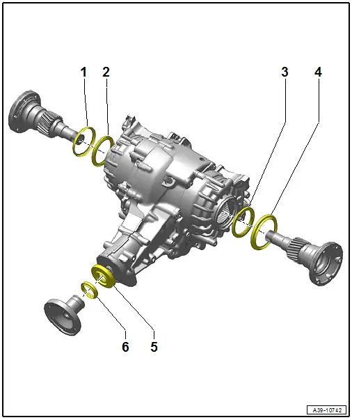
1 - Right Protective Ring
2 - Right Seal
3 - Left Seal
4 - Left Ring
5 - Input Shaft Seal
6 - Input Shaft Ring

