Audi Q7: Component Location Overview - Rear Adjustment Motor
Rear Air Distribution Housing Components, "Mid" or "Mix" A/C System
 Note
Note
- Depending on vehicle equipment, there are different versions of the A/C system for the Audi Q7. Make sure to use the correct version and pay attention to the allocation of different components. Refer to → Chapter "A/C System Versions" and Parts Catalog.
- Depending on the production date, there can be different versions of the levers and fasteners on the heater and A/C unit. Refer to the Parts Catalog.
- Apply a small amount of grease to the cam plate guides, the shaft bearings, the toothed segment as well as to the pins on the door levers. Refer to Parts Catalog.
 Caution
Interchange of the wire connections to the temperature sensors or the connectors at the adjustment motors results in problems regarding the regulation of the A/C system.
- Interchanged connectors at the adjustment motors or the temperature sensors are not identified as malfunctions by the Front A/C Display Control Head -E87-.
- Prior to disconnecting connectors or removing electrical components, clearly label them in order to rule out confusion.
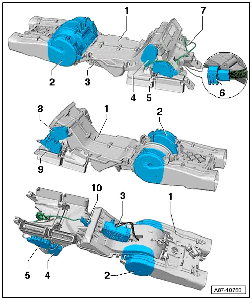
1 - Rear Air Distribution Housing
- Refer to → Chapter "Heater and A/C Unit, Removing and Installing, Mid or Mix A/C System"
- Refer to → Chapter "Overview - Rear Adjustment Motor"
2 - Rear Fresh Air Blower -V80-
- Removing and installing. Refer to → Chapter "Overview - Rear Adjustment Motor".
 Note
Note
In vehicles with a rear air distribution housing, the Rear Fresh Air Blower -V80- is delivered with the rear air distribution housing as a replacement part. Refer to → Chapter "Overview - Rear Adjustment Motor" and the Parts Catalog.
- Ensure the correct allocation. Refer to the Parts Catalog.
- Check. Refer to Vehicle Diagnostic Tester in the "Guided Fault Finding" function
3 - Rear Fresh Air Blower Control Module -J391-
- Refer to → Chapter "Fresh Air Blower Control Module, Removing and Installing "
- Ensure the correct allocation. Refer to the Parts Catalog.
- Check. Refer to Vehicle Diagnostic Tester in the "Guided Fault Finding" function
4 - Left Rear Upper Body Vent Motor -V315-
- Refer to → Chapter "Left Rear Upper Body Vent Motor -V315-"
5 - Left B-Pillar/Footwell Shut-Off Door Motor -V212-
- Refer to → Chapter "Left B-Pillar/Footwell Shut-Off Door Motor -V212-, Removing and Installing"
6 - 10-Pin Harness Connector
- Connection point between the wiring harness at the rear air distribution housing and the vehicle wiring harness. Refer to → Wiring diagrams, Troubleshooting & Component locations.
7 - Wiring Harness at the Rear Air Distribution Housing
8 - Right Rear Upper Body Vent Motor -V316-
- Refer to → Chapter "Right Rear Upper Body Vent Motor -V316-"
9 - Right B-Pillar/Footwell Shut-Off Door Motor -V211-
- Refer to → Chapter "Right B-Pillar/Footwell Shut-Off Door Motor -V211-, Removing and Installing"
10 - Rear Upper Body Vent Temperature Sensor -G537-
- Refer to → Chapter "Rear Upper Body Vent Temperature Sensor -G537-, Removing and Installing"
- Check. Refer to Vehicle Diagnostic Tester in the "Guided Fault Finding" function
 Note
Note
Can only be replaced with the rear air distribution housing removed.
Rear Heater and A/C Unit Components, "High" A/C System
 Note
Note
- Depending on vehicle equipment, there are different versions of the A/C system for the Audi Q7. Make sure to use the correct version and pay attention to the allocation of different components. Refer to → Chapter "A/C System Versions" and Parts Catalog.
- Depending on the production date, there can be different versions of the levers and fasteners on the heater and A/C unit. Refer to the Parts Catalog.
- Apply a small amount of grease to the cam plate guides, the shaft bearings, the toothed segment as well as to the pins on the door levers. Refer to Parts Catalog.
 Caution
Interchange of the wire connections to the temperature sensors or the connectors at the adjustment motors results in problems regarding the regulation of the A/C system.
- Interchanged connectors at the adjustment motors or the temperature sensors are not identified as malfunctions by the Front A/C Display Control Head -E87-.
- Prior to disconnecting connectors or removing electrical components, clearly label them in order to rule out confusion.
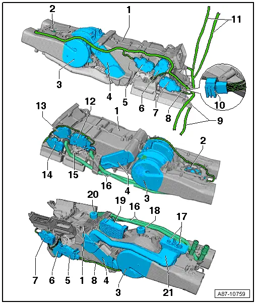
1 - Rear Heater and A/C Unit
- Refer to → Chapter "Heater and A/C Unit, Removing and Installing, High A/C System"
2 - Rear Recirculation Door Motor -V421-
- Refer to → Chapter "Rear Recirculation Door Motor -V421-, Removing and Installing"
3 - Rear Fresh Air Blower -V80-
- Refer to → Chapter "Rear Fresh Air Blower -V80-, Removing and Installing"
- Ensure the correct allocation. Refer to the Parts Catalog.
- Check. Refer to Vehicle Diagnostic Tester in the "Guided Fault Finding" function
4 - Evaporator
- Removing and installing (only possible with the rear heater and A/C unit removed). Refer to → Chapter "Evaporator, Removing and Installing".
- Check the bonded foam seal. It must not be damaged and must be properly glued on.
5 - Left Rear Temperature Control Door Motor -V313-
- Refer to → Chapter "Left Rear Temperature Control Door Motor -V313-, Removing and Installing"
6 - Left Rear Upper Body Vent Motor -V315-
- Refer to → Chapter "Left Rear Upper Body Vent Motor -V315-"
7 - Left B-Pillar/Footwell Shut-Off Door Motor -V212-
- Refer to → Chapter "Left B-Pillar/Footwell Shut-Off Door Motor -V212-, Removing and Installing"
8 - Wiring Harness on Rear Heater and A/C Unit
9 - Wiring Harness to the Temperature Sensors in the Left Front Footwell
- Refer to → Chapter "Left Rear Upper Body Vent Temperature Sensor -G635-, Removing and Installing"
- Refer to → Chapter "Left Rear Footwell Vent Temperature Sensor -G637-, Removing and Installing"
10 - 10-Pin Harness Connector
- Connection point between the wiring harness on the rear heater and A/C unit and the vehicle wiring harness. Refer to → Wiring diagrams, Troubleshooting & Component locations.
11 - Wiring Harness to the Temperature Sensors in the Right Front Footwell
- Refer to → Chapter "Right Rear Upper Body Vent Temperature Sensor -G636-, Removing and Installing"
- Refer to → Chapter "Right Rear Footwell Vent Temperature Sensor -G638-, Removing and Installing"
12 - Right Rear Temperature Control Door Motor -V314-
- Refer to → Chapter "Right Rear Temperature Control Door Motor -V314-, Removing and Installing"
13 - Right Rear Upper Body Vent Motor -V316-
- Refer to → Chapter "Right Rear Upper Body Vent Motor -V316-"
14 - Right B-Pillar/Footwell Shut-Off Door Motor -V211-
- Refer to → Chapter "Right B-Pillar/Footwell Shut-Off Door Motor -V211-, Removing and Installing"
15 - Rear Heater Core
- Refer to → Chapter "Heater Core, Removing and Installing"
 Note
Note
The rear heat exchanger remains in the vehicle when removing the rear heater and A/C unit (so that the coolant circuit does not need to be opened). Refer to → Chapter "Heater and A/C Unit, Removing and Installing, High A/C System".
- Check the bonded foam seal before installing. Refer to → Chapter "Heater Core, Removing and Installing".
- Bleeding the rear coolant circuit. Refer to → Chapter "Heater Core, Removing and Installing".
16 - Coolant Lines
- To the heater core in the rear heater and A/C unit
- These coolant lines are connected to the coolant circuit via coolant hoses running at the bottom of the center tunnel.
 Note
Note
- The air duct to the Rear Fresh Air Blower -V80- must be removed so that these coolant lines can be removed. Refer to → Chapter "Rear Fresh Air Blower -V80-, Removing and Installing".
- These coolant lines are connected to the coolant circuit via coolant hoses running in the center tunnel.
17 - Evaporator Connection to the Refrigerant Lines
- The evaporator is connected to the coolant circuit via coolant lines running at the bottom of the center tunnel.
- Removing and installing. Refer to → Chapter "Evaporator, Removing and Installing".
18 - Condensation Water Drain with Foam Seal
- Condensation water drain under the Rear Fresh Air Blower -V80-.
- Checking. Refer to → Chapter "Condensation Water Drain Hose, Checking".
19 - Rear Fresh Air Blower Control Module -J391-
- Refer to → Chapter "Fresh Air Blower Control Module, Removing and Installing "
- Ensure the correct allocation. Refer to the Parts Catalog.
- Check. Refer to Vehicle Diagnostic Tester in the "Guided Fault Finding" function
20 - Condensation Water Drain with Foam Seal
- Condensation water drain under the evaporator in the rear heater and A/C unit
- In the version of the heat shield in the center tunnel installed at the start of production, this condensation water drain can be checked from below with the exhaust system and the driveshaft installed (the heat shield in the center tunnel ends before the drain). If a longer heat shield is inserted at a later time, the rear heater and A/C unit or the heat shield in the center tunnel must be removed to check the condensation water drain.
- Checking. Refer to → Chapter "Condensation Water Drain Hose, Checking".
21 - Refrigerant Lines to Evaporator in Rear Heater and A/C Unit
- The evaporator is connected to the coolant circuit via coolant lines running at the bottom of the center tunnel.
- Removing and installing. Refer to → Chapter "Evaporator, Removing and Installing".

