Audi Q7: Control Arm Ball Bearing, Replacing
Control Arm Ball Bearing, Replacing, Wheel Bearing Housing Side
Special tools and workshop equipment required
- Press Plate -VW402-
- Press Piece - Multiple Use -VW412-
- Press Piece - 42mm -VW516-
- Press Piece - Reverse Gear Syncro -3296-
- Assembly Paste -G 052 109 A2-
Procedure
- The control arm is removed. Refer to → Chapter "Control Arm, Removing and Installing".
Pressing out the Bonded Rubber Bushing
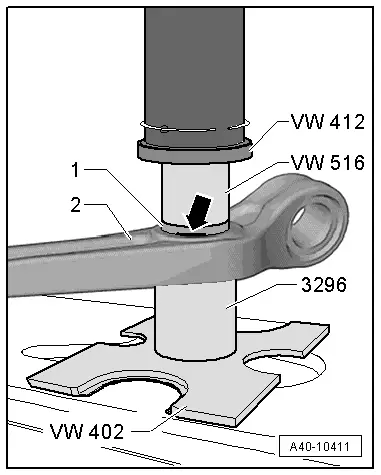
- Mark the press-in depth of the bonded rubber bushing -1- for example using a waterproof felt-tip pen -arrow-.
- Mount the special tools as shown.
 Note
Note
Hold the control arm firmly in position while pressing bonded rubber bushing out and in.
- Press out the bonded rubber bushing from the control arm -2-.
Installing the Bonded Rubber Bushings
- Transfer the marking for the press-in depth from the old bonded rubber bushing to the new one.
- Thinly coat the bonded rubber bushing with the Assembly Paste -G 052 109 A2-.
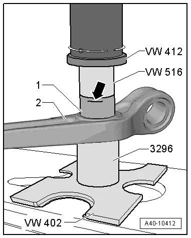
- Insert the bonded rubber bushing -1- in the control arm -2-.
- Mount the special tools as shown.
- Press the bonded rubber bushing in the control arm, at the same time do not tilt it.
- Pay attention to the mark -arrow- for the press-in depth.
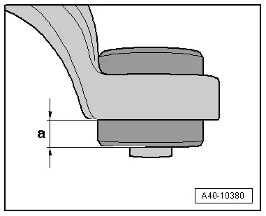
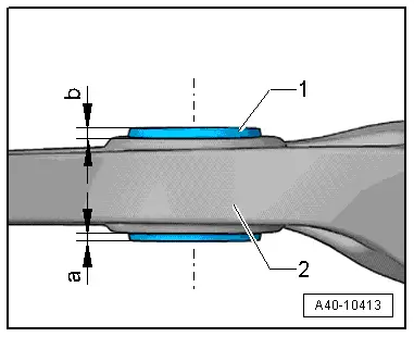
- Check the press-in depth of the bonded rubber bushing -1- in the control arm -2-.
- Specified value: dimension -a- = dimension -b-.
- If the values are different, press in the bonded rubber bushing again.
Control Arm Ball Bearing, Replacing, Subframe Side
Special tools and workshop equipment required
- Press Plate -VW402-
- Press Piece - Multiple Use -VW412-
- Press Piece - Reverse Gear Syncro -3296-
- Puller - Differential Bearing -T40032-
- Assembly Paste -G 052 109 A2-
Procedure
- The control arm is removed. Refer to → Chapter "Control Arm, Removing and Installing".
Pressing out the Bonded Rubber Bushing
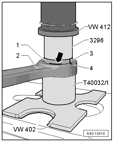
- Mark the press-in depth -arrow- and the installation position -3 and 4- on the bonded rubber bushing -1- with for example a waterproof felt-tip pen as shown.
- Mount the special tools as shown.
 Note
Note
Hold the control arm firmly in position while pressing bonded rubber bushing out and in.
- Press out the bonded rubber bushing from the control arm -2-.
Installing the Bonded Rubber Bushings
- Transfer the marking for the press-in depth from the old bonded rubber bushing to the new one.
- Thinly coat the bonded rubber bushing with the Assembly Paste -G 052 109 A2-.
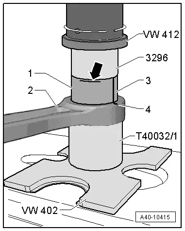
- Insert the bonded rubber bushing -1- in the control arm -2- and align to the mark -3- to -4-.
- Mount the special tools as shown.
- Press the bonded rubber bushing in the control arm, at the same time do not tilt it.
- Pay close attention to the press-in depth mark -arrow-.
- Check the press-in depth of the bonded rubber bushing -1- in the control arm -2-.
- Specified value: dimension -a- = dimension -b-.
- If the values are different, press in the bonded rubber bushing again.

Ball Joint, Removing and Installing
Special tools and workshop equipment required
- Torque Wrench 1332 40-200Nm -VAG1332-
- Torque Wrench 1332 Insert - Ring Wrench - 21mm -VAG1332/7-
- Ball Joint Splitter -T40277-
Removing
- The control arm is removed. Refer to → Chapter "Control Arm, Removing and Installing".
 WARNING
Risk of injury from falling components!
When pressing off, the ball joint loosens abruptly from the control arm. Secure the Ball Joint Splitter -T40277-.
- Clamp the control arm in a vise with protective covers.
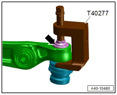
- To protect the threads remove the nut -arrow- on the joint pin of the ball joint until it is flush with the threads of the joint pin.
- Press off the ball joint with the Ball Joint Splitter -T40277- from the control arm, at the same time do not damage the CV boot.
- Then remove the nuts and the ball joint, to do so counterhold on the joint pin with a TX 40 socket.
Installing
Install in reverse order of removal.
Guide Link Bonded Rubber Bushing, Removing and Installing
Special tools and workshop equipment required
- Press Plate -VW402-
- Press Piece - Multiple Use -VW412-
- Bearing Installer - Ball Joint/Bushing/Bearing 2 -VW459/2-
- Bearing Installer - Wheel Bearing -3144-
- Pneumatic Hydraulic Press -VAS6654-, not illustrated
- Installation Lubricant -G 294 421 A1-. Refer to the Parts Catalog.
Pressing out the Bonded Rubber Bushing
- The guide link is removed. Refer to → Chapter "Guide Link, Removing and Installing"
- Mark the press-in depth -arrow- of the bonded rubber bushing -1- for example using a waterproof felt-tip pen.
- Mount the special tools as shown.
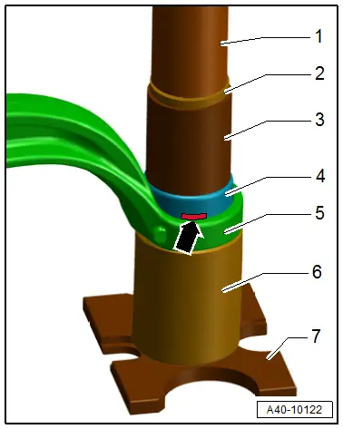
1 - Pneumatic Hydraulic Press -VAS6654- Punch
2 - Press Piece - Multiple Use -VW412-
3 - Bearing Installer - Ball Joint/Bushing/Bearing 2 -VW459/2-
4 - Bonded Rubber Bushing
5 - Guide link
6 - Bearing Installer - Wheel Bearing -3144-
7 - Press Plate -VW402-
 Note
Note
Hold the guide link firmly in position while pressing bonded rubber bushing out and in.
- Remove the bonded rubber bushing from the guide link.
Installing the Bonded Rubber Bushings
- Transfer the marking for the press-in depth from the old bonded rubber bushing to the new one.
- Coat the new bonded rubber bushings thinly with Installation Lubricant -G 294 421 A1-.
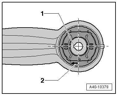
Bonded rubber bushing installation position:
- The notch -1- is on the steering axle and faces inward to the guide link.
- The arrow -2- points inward to the guide link.
- Install the bonded rubber bushing in the guide link. Pay attention to the installed position
- Mount the special tools as shown.

1 - Pneumatic Hydraulic Press -VAS6654- Punch
2 - Press Piece - Multiple Use -VW412-
3 - Bearing Installer - Ball Joint/Bushing/Bearing 2 -VW459/2-
4 - Bonded Rubber Bushing
5 - Guide link
6 - Bearing Installer - Wheel Bearing -3144-
7 - Press Plate -VW402-
- Press the bonded rubber bushing in the guide link, at the same time do not tilt it.
- Pay attention to the mark -arrow- for the press-in depth.
- Check the depth -a- of the bonded rubber bushing inside the guide link.
- Dimension -a- = 23 mm.
- If the value is not reached, press in the bonded rubber bushing again.