Audi Q7: Overview - Drive Axle
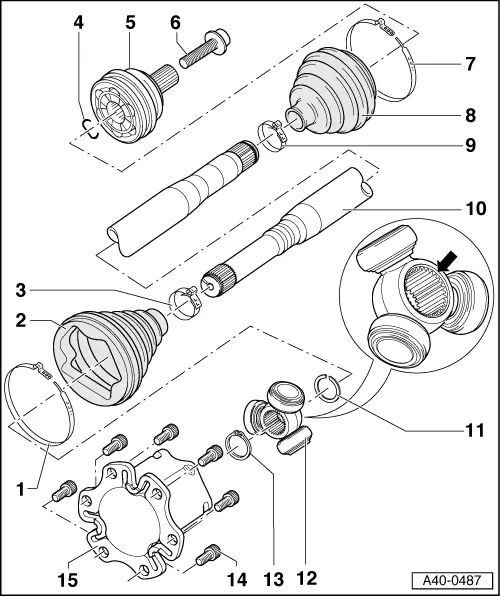
1 - Clamp
- Replace after removing
- Tensioning. Refer to → Chapter "Clamp on Triple Roller Joint and Outer Joint, Tensioning".
2 - CV Boot
- If the drive axle has a peened triple roller joint AAR 3300 i, then the triple roller joint has an adapter installed
- Protective joint boot must fit in groove and on joint contour.
3 - Clamp
- Replace after removing
- Tensioning. Refer to → Chapter "Clamp on Triple Roller Joint and Outer Joint, Tensioning".
4 - Circlip
- Replace after removing
- Insert into ring groove of shaft before installation (not visible on installed joint)
- Before installing CV joint, align sealing ring in center with opening facing upward.
5 - Outer CV Joint
- Completely replace
- For removing.
- Checking. Refer to → Chapter "Outer CV Joint, Checking".
- For installing.
- For greasing.
- Before installing the CV joint thinly coat the profile shaft splines with the grease used in the joint.
6 - Bolt
- Replace after removing
- Clean the threads in the CV joint with for example a thread tap.
- Drive Axle Threaded Connection, Loosening and Tightening. Refer to → Chapter "Drive Axle Threaded Connection, Loosening and Tightening".
7 - Clamp
- Replace after removing
- Tensioning. Refer to → Chapter "Clamp on Triple Roller Joint and Outer Joint, Tensioning".
8 - CV Boot
- Check for tears and scuffing
9 - Clamp
- Replace after removing
- Tensioning. Refer to → Chapter "Clamp on Triple Roller Joint and Outer Joint, Tensioning".
10 - Drive Axle
- Different versions:
- Triple roller joint AAR 3300 i with an outer CV joint with an 94 mm diameter.
- Triple roller joint AAR 3700 i with an outer CV joint with an 98.9 mm diameter.
- Triple roller joint AAR 3700 i with an outer CV joint with an 102.7 mm diameter.
- Allocation. Refer to the Parts Catalog.
- Removing and installing. Refer to → Chapter "Drive Axle, Removing and Installing".
- Triple roller joint allocation. Refer to → Fig. "Triple Roller Joint Allocation.".
- Drive Axle, Disassembling and Assembling. Refer to → Chapter "Drive Axle, Disassembling and Assembling".
11 - Circlip
- Replace after removing
- Insert in shaft groove
12 - Triple Roller Star
- Mark the installed position for reinstallation.
- Disassembling and assembling. Refer to → Chapter "Drive Axle, Disassembling and Assembling".
- Before installing the triple roller star thinly coat the profile shaft splines with the grease used in the joint.
13 - Circlip
- Replace after removing
- Insert in shaft groove
14 - Bolt
- M10: 50 Nm +90º
- M12: 90 Nm +90º
- Replace after removing
15 - Joint
- Disassembling and assembling. Refer to → Chapter "Drive Axle, Disassembling and Assembling".
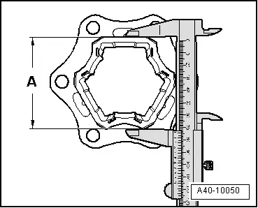
Triple Roller Joint Allocation.
- Determine the dimension -A- with the clamps open and the CV boot pushed back.
- Dimension -A- = approximately 76 mm: drive axle with triple roller joint AAR 3300 i
- Drive Axle Triple Roller Joint AAR 3300 i, Disassembling and Assembling. Refer to → Chapter "Drive Axle, Disassembling and Assembling, Triple Roller Joint AAR 3300i".
- Dimension -A- = approximately 82 mm: drive axle with triple roller joint AAR 3700 i
- Drive Axle Triple Roller Joint AAR 3700 i, Disassembling and Assembling. Refer to → Chapter "Drive Axle, Disassembling and Assembling, Triple Roller Joint AAR 3700i".
Grease Quantity and Type
Grease joint again when replacing protective joint boot.
Grease type. Refer to Parts Catalog.
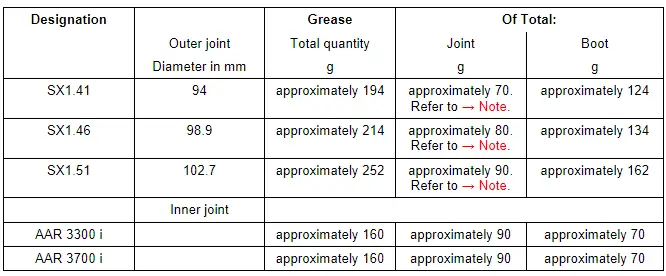
1) This amount goes into the joint through the inner splines on the ball hub. Apply the remainder on the front side of the joint under the boot.

