Audi Q7: Wheel Bearing
Overview - Wheel Bearing
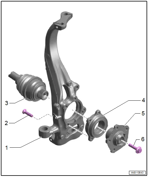
1 - Wheel Bearing Housing
- Removing and installing. Refer to → Chapter "Wheel Bearing Housing, Removing and Installing".
2 - Bolt
- 80 Nm +90º
- Replace after removing
3 - Drive Axle
4 - Wheel Bearing
- Wheel bearing unit, removing and installing. Refer to → Chapter "Wheel Bearing Unit, Removing and Installing".
- Removing and installing. Refer to → Chapter "Wheel Bearing Unit, Servicing".
- Operating. Refer to → Fig. "Operating the Wheel Bearing"
5 - Wheel Hub
- Removing and installing. Refer to → Chapter "Wheel Bearing Unit, Servicing".
6 - Bolt
- Replace after removing
- Before installing, clean the threads in the CV joint with a thread tap.
- Drive Axle Threaded Connection, Loosening and Tightening. Refer to → Chapter "Drive Axle Threaded Connection, Loosening and Tightening".
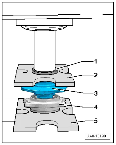
Operating the Wheel Bearing
 Caution
Risk of contaminating and damaging the seal.
- The wheel bearing -1- must face up in order to remove the wheel bearing unit.
- Always set the wheel bearing unit down on the wheel hub -2-.
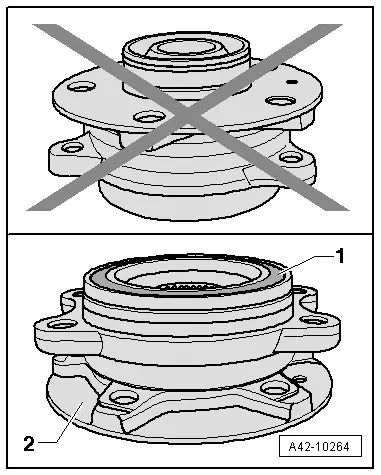
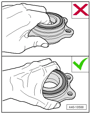
- Never reach inside when lifting the wheel bearing.
- Hold the wheel bearing only on the outside.
Wheel Bearing Housing, Removing and Installing
Special tools and workshop equipment required
- Torque Wrench 1332 40-200Nm -VAG1332-
- Engine and Gearbox Jack -VAS6931-
- Tensioning Strap -T10038-
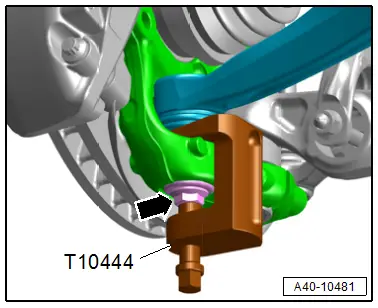
- Ball Joint Removal Tool -T10444-
Removing
Before starting work:
- Versions with coil springs: determine the curb weight position. Refer to → Chapter "Wheel Bearing in Curb Weight Position, Lifting Vehicles with Coil Spring".
- Versions with air suspension: determine the standard vehicle height. Refer to → Chapter "Wheel Bearing at Standard Vehicle Height, Lifting Vehicles with Air Suspension".
- Loosen the connection between the drive axle and wheel hub. Refer to → Chapter "Drive Axle Threaded Connection, Loosening and Tightening".
- Remove the wheel housing liner front section. Refer to → Body Exterior; Rep. Gr.66; Wheel Housing Liner; Front Wheel Housing Liner, Removing and Installing.
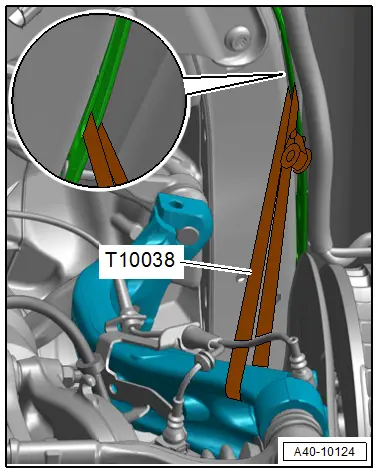
 Caution
There is a risk of damaging the joints of the upper control arms.
The wheel bearing housing must be supported.
- Tie up wheel bearing housing using a Tensioning Strap -T10038- as shown in illustration.
- Remove the front ABS wheel speed sensor. Refer to → Break System; Rep. Gr.45; Sensors; Right and Left Front ABS Wheel Speed Sensor G45/G47, Removing and Installing.
- Remove the brake shield. Refer to → Brake System; Rep. Gr.46; Front Brakes; Brake Shield, Removing and Installing.
- Remove the control arm. Refer to → Chapter "Control Arm, Removing and Installing".
- To protect the threads remove the nut -arrow- on the guide link joint pin until it is flush with the threads of the joint pin. If necessary counterhold the joint pin.
 WARNING
Risk of injury from falling components!
When pressing off, the ball joint loosens abruptly from the wheel bearing housing. Use, for example, the Engine and Gearbox Jack -VAS6931- to secure.
- Remove the guide link joint pin with the Ball Joint Removal Tool -T10444- from the conical seat, at the same time do not damage the CV boot.
- Remove the nut and free up the guide link on the wheel bearing housing to do so if necessary counterhold the joint pin with a TX 40 socket.
 Caution
There is a risk of damaging the wheel bearing housing.
The slits in the wheel bearing housing must not be widened using a chisel or similar tool!
- Disconnect the threaded connection -1-.
- Remove the joint pins in the upper control arm -2- from the wheel bearing housing.
- Loosen the Tensioning Strap -T10038- and remove the wheel bearing housing from drive axle splines.
- Tie up the drive axle.
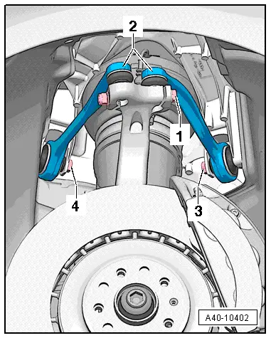
 Note
Note
- The drive axle must not hang down, otherwise the inner joint will be damaged by over bending.
- Ignore -3 and 4-.
Installing
Install in reverse order of removal and note the following:
- Slide the wheel bearing housing onto the drive axle splines.
- Install the control arm. Refer to → Chapter "Control Arm, Removing and Installing".
- Install the upper control arm. Refer to → Chapter "Upper Control Arm, Removing and Installing".
- Install the brake shield. Refer to → Brake System; Rep. Gr.46; Front Brakes; Brake Shield, Removing and Installing.
- Tighten the drive axle to wheel hub threaded connection. Refer to → Chapter "Drive Axle Threaded Connection, Loosening and Tightening".
- Overview table for if an axle alignment is necessary. Refer to → Chapter "Need for Axle Alignment, Evaluating".
Tightening Specifications
- Refer to → Chapter "Overview - Wheel Bearing"
- Refer to → Chapter "Overview - Lower Control Arm and Ball Joint"
- Refer to → Body Exterior; Rep. Gr.66; Wheel Housing Liner; Overview - Front Wheel Housing Liner.
Wheel Bearing Unit, Removing and Installing
Special tools and workshop equipment required
- Torque Wrench 1332 40-200Nm -VAG1332-
Removing
 Caution
Risk of damage or contamination to the wheel bearing.
Operating the wheel bearing.
- Loosen the connection between the drive axle and wheel hub. Refer to → Chapter "Drive Axle Threaded Connection, Loosening and Tightening".
- Remove the brake rotor. Refer to → Brake System; Rep. Gr.46; Front Brakes; Brake Rotor, Removing and Installing.
 Caution
There is a risk of damaging the wheel bearing housing.
The slits in the wheel bearing housing must not be widened using a chisel or similar tool!
- Disconnect the threaded connection -1-.
- Remove the joint pins in the upper control arm -2- from the wheel bearing housing.
 Note
Note
Ignore -3 and 4-.

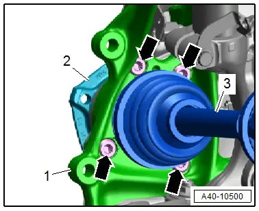
- Remove the bolts -arrows-.
- Remove the wheel hub -2- with the wheel bearing unit from the drive axle -3- and from the wheel bearing housing -1-.
Installing
Install in reverse order of removal and note the following:
- Tighten the drive axle to wheel hub threaded connection. Refer to → Chapter "Drive Axle Threaded Connection, Loosening and Tightening".
Tightening Specifications
- Refer to → Chapter "Overview - Wheel Bearing"
- Refer to → Chapter "Wheels and Tires"
Wheel Bearing Unit, Servicing
Special tools and workshop equipment required
- Press Plate -VW401-
- Press Plate -VW402-
- Press Piece - Multiple Use -VW412-
- Hydraulic Press - Bushing Assembly Tool Kit -T10230-
- Pneumatic Hydraulic Press -VAS6654-
- Puller Set VAS701003 -VAS701003-
- Puller Set - Clamping Sleeve -VAS701003/1-
- Puller Set - Threaded Spindle -VAS701003/2-
- Puller Set - Clamping Handle -VAS701003/4-
- Puller Set - Special Ring Spanner AF36 -VAS701003/5-
- Puller Set - Clamping Pliers, Diameter 66-70 mm -VAS701003/7-
Procedure
- Wheel bearing housing is removed. Refer to → Chapter "Wheel Bearing Unit, Removing and Installing".
Wheel Hub, Removing from Wheel Bearing
- Mount the special tools as shown.
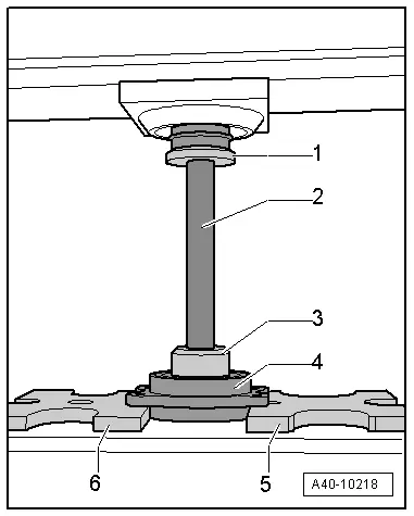
1 - Press Piece - Multiple Use -VW412-
2 - Hydraulic Press - Bushing Assembly Tool Kit - Sleeve -T10230/3-
3 - Hydraulic Press - Bushing Assembly Tool Kit - Thrust Piece -T10230/8-
4 - Wheel Bearing Unit
5 - Press Plate -VW402-
6 - Press Plate -VW401-
- Press the wheel hub out of the wheel bearing.
Removing the Bearing Inner Race from the Hub
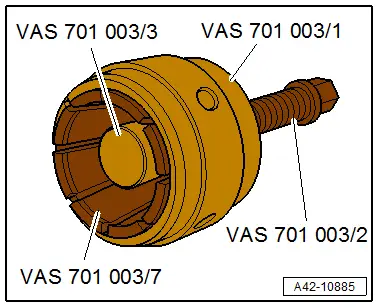
- Prepare the puller from the Puller Set VAS 701 003 -VAS701003- as follows:
- Install the Puller Set - Clamping Sleeve -VAS701003/1- on the Puller Set - Clamping Pliers, Diameter 66-70 mm -VAS701003/7-.
- Install the Puller Set - Threaded Spindle -VAS701003/2- in the adapter sleeve and attach the Puller Set - Thrust Piece -VAS701003/3-.
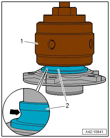
Bearing Inner Race Version 1:
- Remove the ball-cage assembly from the bearing inner race -2-.
- Place the puller -1- as shown on the ball bearing race -arrow- of the bearing inner race.
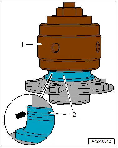
Bearing Inner Race Version 2:
- Place the puller -1- on the groove -arrow- of the bearing inner race -2-.
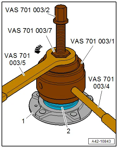
Continuation for All Versions:
- Clamp the puller on the bearing inner race -2- to do so turn the Puller Set - Clamping Pliers, Diameter 66-70 mm -VAS701003/7- with the Puller Set - Special Ring Spanner AF36 -VAS701003/5- in the direction of -arrow- and counterhold the Puller Set - Clamping Sleeve -VAS701003/1- with the Puller Set - Clamping Handle -VAS701003/4-.
- Remove the bearing inner race with the Puller Set - Threaded Spindle -VAS701003/2- from the wheel hub -1-.
Pressing Wheel Hub into Wheel Bearing
- Mount the special tools as shown.
1 - Press Piece - Multiple Use -VW412-
2 - Press Plate -VW402-
3 - Wheel hub
4 - Wheel Bearing
5 - Press Plate -VW401-
- The reworked surface of the wheel bearing outer race faces down.
 Caution
Risk of damage or contamination to the wheel bearing.
When setting down or pressing in, make sure there is no dirt or contaminants between the Press Plate -VW401- and the wheel bearing.
- Press the wheel hub into the wheel bearing.
- Install the wheel bearing unit. Refer to → Chapter "Wheel Bearing Unit, Removing and Installing".

